PowerPC™ 405 Processor Block Reference Guide www.xilinx.com 9
UG018 (v2.0) August 20, 2004 1-800-255-7778
R
Preface
About This Guide
This guide serves as a technical reference describing the hardware interface to the
PowerPC
®
405 processor block. It contains information on input/output signals, timing
relationships between signals, and the mechanisms software can use to control the
interface operation. The document is intended for use by FPGA and system hardware
designers and by system programmers who need to understand how certain operations
affect hardware external to the processor.
Guide Contents
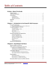
This manual contains the following chapters:
x Chapter 1, “Introduction to the PowerPC 405 Processor,” provides an overview of the
PowerPC embedded-environment architecture and the features supported by the
PowerPC 405.
x Chapter 2, “Input/Output Interfaces,” describes the interface signals into and out of
the PowerPC 405 processor block. Where appropriate, timing diagrams are provided
to assist in understanding the functional relationship between multiple signals.
x Chapter 3, “PowerPC 405 OCM Controller,” describes the features, interface signals,
timing specifications, and programming model for the PowerPC 405 on-chip memory
(OCM) controller. The OCM controller serves as a dedicated interface between the
block RAMs in the FPGA and OCM signals available on the embedded PowerPC 405
core.
x Chapter 4, “PowerPC 405 APU Controller,” describes the Auxiliary Processor Unit
controller, which allows the designer to extend the native PowerPC 405 instruction set
with custom instructions that are executed by an FPGA Fabric Co-processor Module
(FCM). The APU controller is available only for Virtex-4 family devices.
x Appendix A, “RISCWatch and RISCTrace Interfaces,” describes the interface
requirements between the PowerPC 405 processor block and the RISCWatch and
RISCTrace tools.
x Appendix B, “Signal Summary,” lists all PowerPC 405 interface signals in alphabetical
order.
x Appendix C, “Processor Block Timing Model,” explains all of the timing parameters
associated with the IBM PPC405 Processor Block.


