


PowerPC™ 405 Processor Block Reference Guide www.xilinx.com 105
UG018 (v2.0) August 20, 2004 1-800-255-7778
R
External DCR Bus Interface I/O Signal Descriptions
The following sections describe the operation of the DCR interface I/O signals. Signals are
presented with both Virtex-II Pro and Virtex-4-FX names.
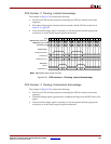
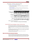
C405DCRREAD/EXTDCRREAD (Output)
When asserted, this signal indicates the processor block is requesting the contents of a DCR
(reading from the DCR) in response to the execution of a move-from DCR instruction
(mfdcr). The contents of the DCR address bus are valid when this request is asserted.
In Virtex-II Pro/ProX the request is asserted one CPMC405CLOCK cycle after the
processor block begins driving the DCR address bus and it is deasserted two cycles after
the DCR acknowledge signal is asserted. In Virtex-4-FX the request is asserted in the same
CPMDCRCLK cycle as, or one cycle after, the processor block begins driving the DCR
address bus and it is deasserted at least one cycle after the DCR acknowledge signal is
asserted. DCR read requests are not interrupted by the processor block. If this signal is
asserted, only a DCR acknowledgement or read time-out will deassert it. For details see
signal “DCRC405ACK/EXTDCRACK (Input)”.
This signal is deasserted during reset.
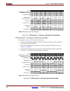
C405DCRWRITE/EXTDCRWRITE (Output)
When asserted, this signal indicates the processor block is requesting that the contents of a
DCR be updated (writing to the DCR) in response to the execution of a move-to DCR
instruction (mtdcr).
In Virtex-II Pro/ProX the request is asserted one CPMC405CLOCK cycle after the
processor block begins driving the DCR address and write-data bus. It is deasserted two
cycles after the DCR acknowledge signal is asserted. In Virtex-4-FX the request is asserted
in the same CPMDCRCLK cycle as, or one cycle after, the processor block begins driving
the DCR address and write-data bus. It is deasserted at least one cycle after the DCR
acknowledge signal is asserted. DCR write requests are not interrupted by the processor
block. If this signal is asserted, only a DCR acknowledgement or write time-out will
deassert it. For details see signal “DCRC405ACK/EXTDCRACK (Input)”.
This signal is deasserted during reset.
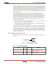
C405DCRABUS[0:9]/EXTDCRABUS[0:9] (Output)
This bus specifies the address of the DCR access request. This bus remains stable during
the execution of a mfdcr or mtdcr instruction. However, the contents of this bus are valid
only when either a DCR read request or DCR write request are asserted by the processor.
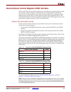
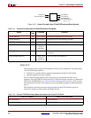
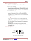
EXTDCRABUS[0:9] C405DCRABUS[0:9]
EXTDCRDBUSOUT[0:31] C405DCRDBUSOUT[0:31]
EXTDCRACK DCRC405ACK
EXTDCRDBUSIN[0:31] DCRC405DBUSIN[0:31]
Table 2-22: Virtex-4-FX DCR Interface Name Correlation with Virtex-II Pro/ProX (Continued)
Virtex-4-FX Name Virtex-II Pro/ProX Name