


PowerPC™ 405 Processor Block Reference Guide www.xilinx.com 39
UG018 (v2.0) August 20, 2004 1-800-255-7778
R
C405CPMMSREE, C405CPMMSRCE, and C405CPMTIMERIRQ signals before using them
to control the processor clocks.
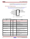
C405CPMTIMERIRQ (Output)
When asserted, this signal indicates a timer exception occurred within the PowerPC 405
and an interrupt request is pending to handle the exception. When deasserted, no timer-
interrupt request is pending. This signal is the logical OR of interrupt requests from the
programmable-interval timer (PIT), the fixed-interval timer (FIT), and the watchdog timer
(WDT). The CPM can use this signal to wake the processor from sleep mode when an
internal timer exception occurs.
When the processor wakes up, it deasserts the C405CPMMSREE, C405CPMMSRCE, and
C405CPMTIMERIRQ signals one processor clock cycle before it deasserts the
C405CPMCORESLEEPREQ signal. Consequently, the CPM should latch the
C405CPMMSREE, C405CPMMSRCE, and C405CPMTIMERIRQ signals before using them
to control the processor clocks.
C405CPMTIMERRESETREQ (Output)
When asserted, this signal indicates a watchdog time-out occurred and a reset request is
pending. When deasserted, no reset request is pending. This signal is the logical OR of the
core, chip, and system reset modes that are programmed using the watchdog timer
mechanism. The CPM can use this signal to wake the processor from sleep mode when a
watchdog time-out occurs.
C405CPMCORESLEEPREQ (Output)
When asserted, this signal indicates the PowerPC 405 has requested to be put into sleep
mode. When deasserted, no request exists. This signal is asserted after software enables the
wait state by setting the MSR[WE] (wait-state enable) bit to 1. The processor completes
execution of all prior instructions and memory accesses before asserting this signal. The
CPM can use this signal to place the processor in sleep mode at the request of software.
When the processor gets out of sleep mode at a later time, it deasserts the
C405CPMMSREE, C405CPMMSRCE, and C405CPMTIMERIRQ signals one processor
clock cycle before it deasserts the C405CPMCORESLEEPREQ signal. Consequently, the
CPM should latch the C405CPMMSREE, C405CPMMSRCE, and C405CPMTIMERIRQ
signals before using them to control the processor clocks.
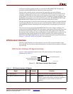
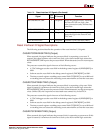
System Design Considerations for Clock Domains
The high-level view of an embedded system with the PowerPC 405 processor and
CoreConnect bus architecture includes:
x PowerPC 405 Processor.
x Processor Local Bus (PLB) peripherals.
x Instruction-side and Data-side On-Chip Memory Controller (OCM).
x Device Control Register (DCR) peripherals.
x Fabric Co-Processor Module (FCM): Virtex-4 only.
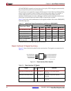
These clocks communicate to the processor block the specific clock ratio between the
processor block clock and the other system clocks in the design.
x CPMC405CLOCK, main Processor Block clock.