


PowerPC™ 405 Processor Block Reference Guide www.xilinx.com 207
UG018 (v2.0) August 20, 2004 1-800-255-7778
R
Appendix A
RISCWatch and RISCTrace Interfaces
This appendix summarizes the interface requirements between the PowerPC 405 and the
RISCWatch and RISCTrace tools.
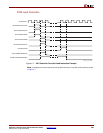
The requirement for separate JTAG and trace connectors is being replaced with a single
Mictor connector to improve the electrical and mechanical characteristics of the interface.
Pin assignments for the Mictor connector are included in the signal-mapping tables.
RISCWatch Interface
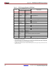
The RISCWatch tool communicates with the PowerPC 405 using the JTAG and debug
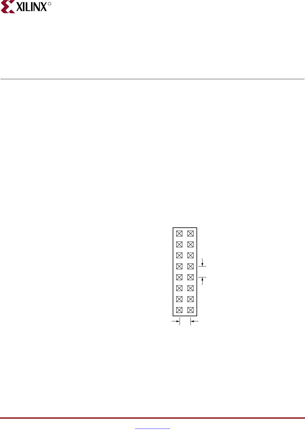
interfaces. It requires a 16-pin, male 2x8 header connector located on the target
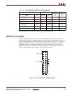
development board. The layout of the connector is shown in Figure A-1 and the signals are
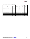
described in Table A-1. A mapping of PowerPC 405 to RISCWatch signals is provided in
Table A-2. At the board level, the connector should be placed as close as possible to the
processor chip to ensure signal integrity. Position 14 is used as a connection key and does
not contain a pin.
Figure A-1: JTAG-Connector Physical Layout
UG018_50_100901
15
1
16
2
0.1"
0.1"