PowerPC™ 405 Processor Block Reference Guide www.xilinx.com 57
UG018 (v2.0) August 20, 2004 1-800-255-7778
R
The ICU reads either the low 32 bits or the high 32 bits of the 64-bit interface,
depending on the value of PLBC405ICURDWDADDR[1:3].
x When a 64-bit PLB slave responds, an aligned doubleword is sent from the slave to the
ICU during each transfer cycle. Both words are read from the 64-bit interface by the
ICU in this cycle.
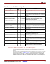
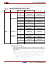
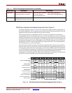
Table 2-10 shows the location of instructions on the ICU read-data bus as a function of PLB-
slave size, line-transfer size, and transfer order.
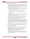
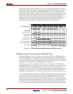
PLBC405ICURDWDADDR[1:3] (Input)
These signals are used to specify the transfer order. They identify which word or
doubleword of a line transfer is present on the ICU read-data bus when the PLB slave
returns instructions to the ICU. The words returned during a line transfer can be sent from
the PLB slave to the ICU in any order (target-word-first, sequential, other). The transfer-
order signals are valid when the read-data acknowledgement signal
(PLBC405ICURDDACK) is asserted. This acknowledgment is asserted for one cycle per
transfer. There is no limit to the number of cycles between two transfers. The transfer-order
signals are not valid when the read-data acknowledgement signal is deasserted.
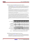
Table 2-10 shows the location of instructions on the ICU read-data bus as a function of PLB-
slave size, line-transfer size, and transfer order. In this table, the Transfer Order column
contains the possible values of PLBC405ICURDWDADDR[1:3]. For 64-bit PLB slaves,
PLBC405ICURDWDADDR[3] should always be 0 during a transfer. In this case, the
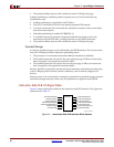
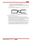
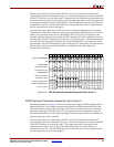
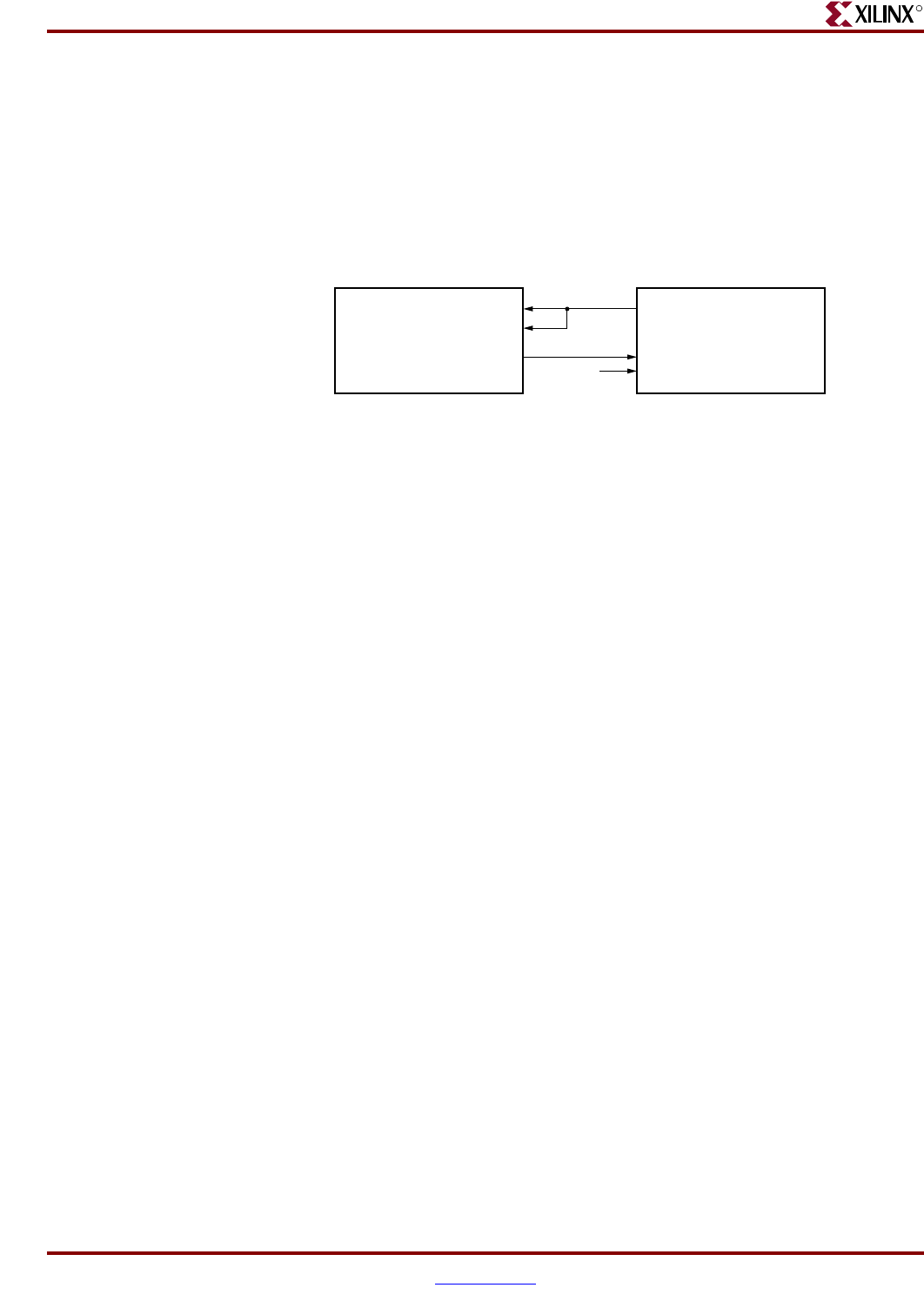
Figure 2-5: Attachment of ISPLB Between 32-Bit Slave and 64-Bit Master
UG018_10_102001
C405PLBICUABUS[0:29]
PLBC405ICURDDBUS[0:31]
PLBC405ICURDDBUS[32:63]
C405PLBICUABUS[0:29]
PLBC405ICURDDBUS[0:31]
00
64-Bit PLB Master 32-Bit PLB Slave
C405PLBICUABUS[30:31]


