PowerPC™ 405 Processor Block Reference Guide www.xilinx.com 161
UG018 (v2.0) August 20, 2004 1-800-255-7778
R
Features Introduced in Virtex-4 and Comparison with Virtex-II Pro
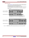
In Virtex-4 an optional auto clock ratio detection feature was implemented on both the
DSOCM and ISOCM. If bit 3 (Enable Auto Clock Ratio Detection) of the DSCNTL/ISCNTL
register(s) is 1, then auto clock ratio detection will take place. This is the recommended
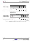
operation model for Virtex-4. Additionally, when DSOCMMCM/ISOCMMCM is read
back, the value of the auto-detected clock ratio is reflected in terms of the wait state value.
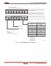
In Virtex-II Pro, the OCM clock cycle modes are selected through the MULTICYCLEMODE
control bits (DSOCMMCM and ISOCMMCM) in the DSCNTL and ISCNTL registers.
Virtex-4 supports a maximum clock ratio of 8:1, and Virtex-II Pro supports a maximum
clock ratio of 4:1. Therefore, Virtex-4 has one more control bit in both the ISOCMMCM and
the DSOCMMCM registers.
Another extended feature in Virtex-4 is the DCR-based read access to the ISOCM to
support software debugging. To enable this feature, bit 2 of the ISCNTL register must be
enabled.
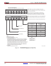
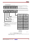
Table 3-12: ISCNTL Register for Virtex-4
Bit 0 ISOCM Enable If set to 1, address decoding based on the value of ISARC will be
enabled. If set to 0, the content in ISARC will be ignored.
Bit 1 Reserved. This bit must be configured to 0.
Bit 2 Enable DCR Based Read
Back
If this bit is set to 1, reading from ISFILL register using an mfdcr
instruction will return the memory content addressed by ISINIT
register. If this bit is set to 0, reading from ISFILL register using a
“mfdcr” instruction will return the previous content of ISFILL
register set by user. This is an enhanced feature in Virtex-4 devices.
Bit 3 Enable Auto Clock Ratio
Detection
If set to 1, automatic clock ratio detection circuits will be enabled
and users do not need to setup the CPU Clock/ISOCM Clock ratio
in ISCNTL[4:7]. Additionally, when ISOCMMCM is read back, the
value of the auto-detected clock ratio is reflected in terms of the wait
state value.
If set to 0, automatic clock ratio detection will be disabled and users
need to setup CPU Clock /ISOCM Clock ratio in ISCNTL[4:7]. This
is an enhanced feature in Virtex-4 devices, and we recommend
setting this bit to 1.
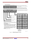
Bit 4:7 ISOCMMCM CPU Clock and OCM Clock ratio. For Virtex-4 devices, if Auto
Clock Ratio Detection is enabled users need not setup the ratio in
this field. Users can also read back this field to determine the clock
ratio detected by the circuits.
If Auto Clock Ratio Detection is disabled, users need to setup the
ratio in this field. Reading back from this field will return the
content set by users previously.


