


PowerPC™ 405 Processor Block Reference Guide www.xilinx.com 131
UG018 (v2.0) August 20, 2004 1-800-255-7778
R
C405DBGSTOPACK (Output)
When asserted, this signal indicates that the PowerPC 405 is in debug halt mode. When
deasserted, the processor is not in debug halt mode.
C405DBGLOADDATAONAPUDBUS (Output, Virtex-4-FX only)
This signal is asserted when there is a valid load data being transferred between the APU
controller logic and the PowerPC 405 core.
Trace Interface
The processor uses the trace interface when operating in real-time trace-debug mode. Real-
time trace-debug mode supports real-time tracing of the instruction stream executed by
the processor. In this mode, debug events are used to cause external trigger events. An
external trace tool (such as RISCTrace) uses the trigger events to control the collection of
trace information. The broadcast of trace information on the trace interface occurs
independently of external trigger events (trace information is always supplied by the
processor). Real-time trace-debug does not affect processor performance.
Real-time trace-debug mode is always enabled. However, the trigger events occur only
when both internal-debug mode and external debug mode are disabled (DBCR0[IDM]=0
and DBCR0[EDM]=0). Most trigger events are blocked when either of those two debug
modes are enabled. See the PowerPC Processor Reference Guide for more information on
debug events.
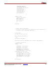
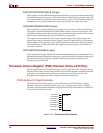
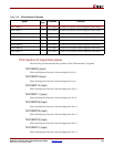
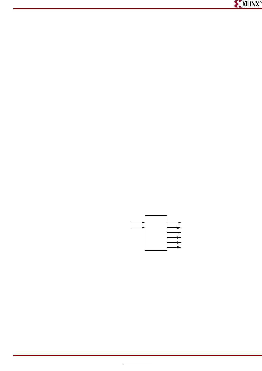
Trace Interface Signal Summary
Figure 2-47 shows the block symbol for the trace interface. The signals are summarized in
Table 2-27. See Appendix A, “RISCWatch and RISCTrace Interfaces” for information on
attaching a RISCTrace to the trace interface signals.
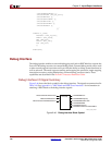
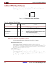
Figure 2-47: Trace Interface Block Symbol
C405TRCTRIGGEREVENTOUT
C405TRCTRIGGEREVENTTYPE[0:10]
C405TRCCYCLE
C405TRCEVENEXECUTIONSTATUS[0:1]
C405TRCODDEXECUTIONSTATUS[0:1]
C405TRCTRACESTATUS[0:3]
UG018_33_020702
PPC405
TRCC405TRIGGEREVENTIN
TRCC405TRACEDISABLE