PowerPC™ 405 Processor Block Reference Guide www.xilinx.com 37
UG018 (v2.0) August 20, 2004 1-800-255-7778
R
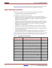
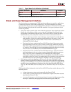
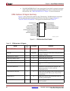
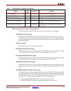
CPM Interface I/O Signal Descriptions
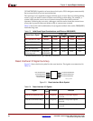
The following sections describe the operation of the CPM interface I/O signals.
CPMC405CLOCK (Input)
This signal is the source clock for all PowerPC 405 logic (including timers). It is not the
source clock for the JTAG logic. External logic can implement a power management mode
that stops toggling of this signal. If such a method is employed, the clock signal should be
held active (logic 1).
PLBCLK (Input)
This signal is the source clock for all PLB logic.
CPMC405CPUCLKEN (Input)
Enables the core clock zone when asserted and disables the zone when deasserted. If logic
is not implemented to control this signal, it must be held active (tied to 1).
CPMC405TIMERCLKEN (Input)
Enables the timer clock zone when asserted and disables the zone when deasserted. If logic
is not implemented to control this signal, it must be held active (tied to 1).
CPMC405JTAGCLKEN (Input)
Enables the JTAG clock zone when asserted and disables the zone when deasserted. CPM
logic should not control this signal. The JTAG standard requires that it be held active (tied
to 1).
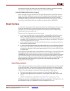
CPMC405CORECLKINACTIVE (Input)
This signal is a status indicator that is latched by an internal PowerPC 405 register (JDSR).
An external debug tool (such as RISCWatch) can read this register and determine that the
PowerPC 405 is in sleep mode. This signal should be asserted by the CPM when it places
the PowerPC 405 in sleep mode using either of the following methods:
x Deasserting CPMC405CPUCLKEN to disable the core clock zone.
x Stopping CPMC405CLOCK from toggling by holding it active (logic 1).
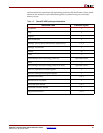
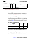
C405CPMMSREE O No Connect Indicates the value of MSR[EE].
C405CPMMSRCE O No Connect Indicates the value of MSR[CE].
C405CPMTIMERIRQ O No Connect Indicates a timer-interrupt request occurred.
C405CPMTIMERRESETREQ O No Connect Indicates a watchdog-timer reset request
occurred.
C405CPMCORESLEEPREQ O No Connect Indicates the core is requesting to be put into
sleep mode.
Table 2-2: CPM Interface I/O Signals (Continued)
Signal
I/O
Type
If Unused Function


