


100 www.xilinx.com PowerPC™ 405 Processor Block Reference Guide
1-800-255-7778 UG018 (v2.0) August 20, 2004
Chapter 2: Input/Output Interfaces
R
In Virtex-II Pro/ProX, a DCR access addressing the internal DCR logic could be visible on
the external DCR bus interface as an access.
Virtex-4-FX
In Virtex-4-FX processor blocks, there are four functional units that contain device-control
registers:
1. The data-side OCM (DSOCM) controller, which contains the DSCNTL and DSARC
registers.
2. The instruction-side OCM (ISOCM) controller, which contains the ISCNTL, ISARC,
ISINIT, and ISFILL registers.
3. The APU Controller, which contains the APUCFG and UDICFG registers.
4. The Ethernet MAC DCR Bus Interface (with a fixed connection to the hard EMAC
controller), which contains the RDYstatus, cntlReg, dataRegLSW, and dataRegMSW
registers.
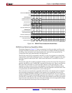
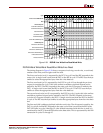
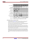
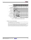
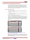
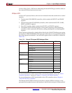
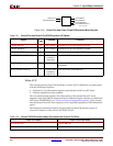
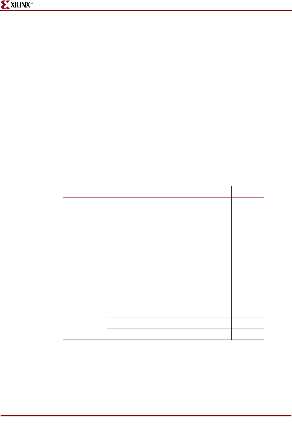
These registers are located in a single address block in the 10-bit DCR address space using
the input port TIEDCRADDR[0:5]. This input port defines the six most significant address
bits of the register block address. The individual register offset in each block is defined in
Table 2-20.
For more information on DCR functionality in the OCM controller, refer to the “OCM
Controller Operation” section of Chapter 3, “PowerPC 405 OCM Controller”.
For more information on DCR functionality in the APU controller, refer to Chapter 4,
“PowerPC 405 APU Controller”.
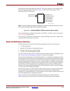
The Ethernet MAC DCR Bus interface looks like a complete DCR bus interface on the
processor block symbol, however, this interface is hard wired to the pair of Ethernet MAC
Table 2-20: Virtex-4-FX Internal DCR Address Offset
Block Device Control Register Offset
EMAC RDYstatus 15
cntlReg 14
dataRegLSW 13
dataRegMSW 12
Reserved - 8:11
DSOCM DSCNT 7
DSARC 6
APU APUCFG 5
UDICFG 4
ISOCM ISCNT 3
ISARC 2
ISFILL 1
ISINIT 0