


PowerPC™ 405 Processor Block Reference Guide www.xilinx.com 45
UG018 (v2.0) August 20, 2004 1-800-255-7778
R
Reset Interface I/O Signal Descriptions
The following sections describe the operation of the reset interface I/O signals.
C405RSTCORERESETREQ (Output)
When asserted, this signal indicates the processor block is requesting a core reset. If
asserted, this signal remains active until two clock cycles after external logic asserts the
RSTC405RESETCORE input to the processor block. When deasserted, no core-reset request
exists.
The processor asserts this signal when one of the following occurs:
x A JTAG debugger sets the reset field in the debug-control register 0 (DBCR0[RST]) to
0b01.
x Software sets the reset field in the debug-control register 0 (DBCR0[RST]) to 0b01.
x The timer-control register watchdog-reset control field (TCR[WRC]) is set to 0b01 and
a watchdog time-out causes the watchdog-event state machine to enter the reset state.
C405RSTCHIPRESETREQ (Output)
When asserted, this signal indicates the processor block is requesting a chip reset. If this
signal is asserted, it remains active until two clock cycles after external logic asserts the
RSTC405RESETCHIP input to the processor block. When deasserted, no chip-reset request
exists. Unlike GSR, this output has no associated reset connectivity in the FPGA.
The processor asserts this signal when one of the following occurs:
x A JTAG debugger sets the reset field in the debug-control register 0 (DBCR0[RST]) to
0b10.
x Software sets the reset field in the debug-control register 0 (DBCR0[RST]) to 0b10.
x The timer-control register watchdog-reset control field (TCR[WRC]) is set to 0b10 and
a watchdog time-out causes the watchdog-event state machine to enter the reset state.
C405RSTSYSRESETREQ (Output)
When asserted, this signal indicates the processor block is requesting a system reset. If this
signal is asserted, it remains active until two clock cycles after external logic asserts the
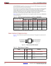
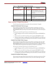
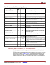
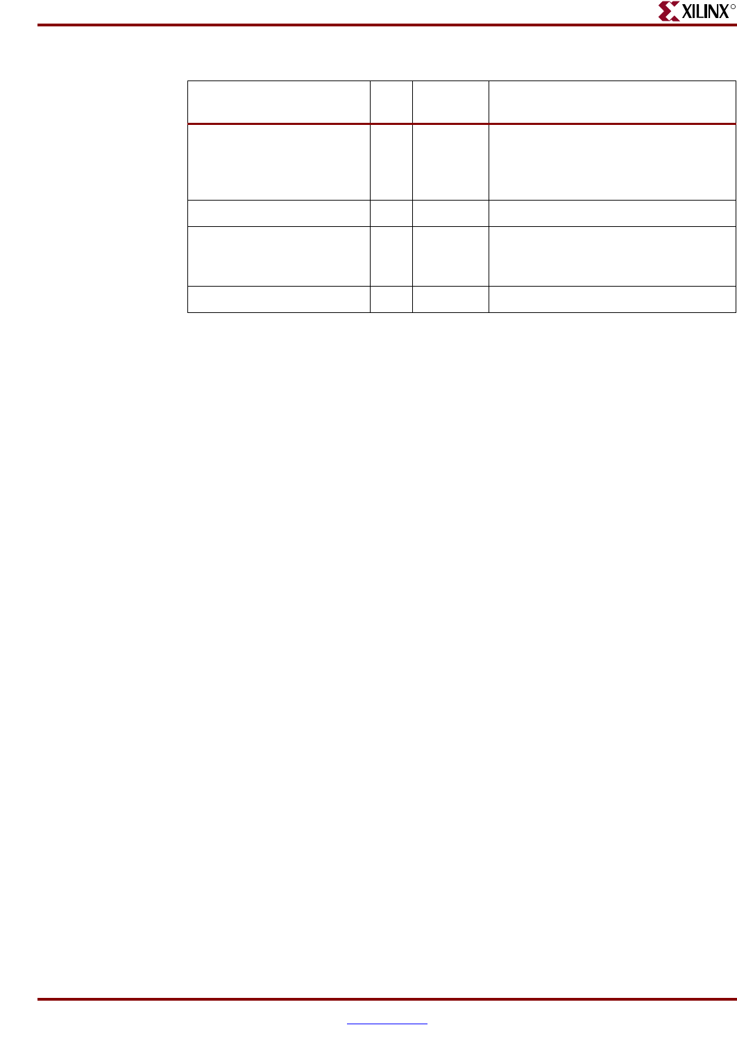
RSTC405RESETCORE I Required Resets the processor block, including
the PowerPC 405 core logic, data
cache, instruction cache, and interface
controllers.
RSTC405RESETCHIP I Required Indicates a chip-reset occurred.
RSTC405RESETSYS I Required Indicates a system-reset occurred.
Resets the logic in the PowerPC 405
JTAG unit.
JTGC405TRSTNEG I Required Performs a JTAG test reset (TRST).
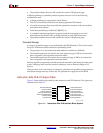
Table 2-6: Reset Interface I/O Signals (Continued)
Signal
I/O
Type
If Unused Function