


76 www.xilinx.com PowerPC™ 405 Processor Block Reference Guide
1-800-255-7778 UG018 (v2.0) August 20, 2004
Chapter 2: Input/Output Interfaces
R
C405PLBDCUU0ATTR (Output)
This signal reflects the value of the user-defined (U0) storage attribute for the target
address. The accessed data is not in a memory location characterized by this attribute
when the signal is deasserted (0). It is in a memory location characterized by this attribute
when the signal is asserted (1). This signal is valid when the DCU is presenting a data-
access request to the PLB slave. The signal remains valid until the cycle following
acknowledgement of the request by the PLB slave. (The PLB slave asserts
PLBC405DCUADDRACK to acknowledge the request.)
The system designer can use this signal to assign special behavior to certain memory
addresses. Its use is optional.
C405PLBDCUGUARDED (Output)
This signal indicates whether the accessed data is in guarded storage. It reflects the value
of the guarded storage attribute for the target address. The data is not in guarded storage
when the signal is deasserted (0). The data is in guarded storage when the signal is asserted
(1). This signal is valid when the DCU is presenting a data-access request to the PLB slave.
The signal remains valid until the cycle following acknowledgement of the request by the
PLB slave (the PLB slave asserts PLBC405DCUADDRACK to acknowledge the request).
No bytes are accessed speculatively from guarded storage. The PLB slave must return only
the requested data when guarded storage is read and update only the specified memory
locations when guarded storage is written. For single word transfers, only the bytes
indicated by the byte enables are transferred. For line transfers, all eight words in the line
are transferred.
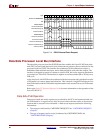
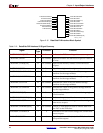
C405PLBDCUBE[0:7] (Output)
These signals, referred to as byte enables, indicate which bytes on the DCU read-data bus
or write-data bus are valid during a word transfer. The byte enables are not used by the
DCU during line transfers and must be ignored by the PLB slave. The byte enables are
valid when the DCU is presenting a data-access request to the PLB slave. They remain
valid until the cycle following acknowledgement of the request by the PLB slave (the PLB
slave asserts PLBC405DCUADDRACK to acknowledge the request).
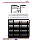
Attachment of a 32-bit PLB slave to the DCU (a 64-bit PLB master) requires the connections
shown in Figure 2-16. These connections enable the byte enables to be presented properly
to the 32-bit slave. Address bit 29 is used to select between the upper byte enables [0:3] and
the lower byte enables [4:7] when making a request to the 32-bit slave. Words are always
transferred to the 32-bit PLB slave using write-data bus bits [0:31], so bits [32:63] are not
connected. The 32-bit read-data bus from the PLB slave is attached to both the high and
low words of the 64-bit read-data bus into the DCU.