


PowerPC™ 405 Processor Block Reference Guide www.xilinx.com 149
UG018 (v2.0) August 20, 2004 1-800-255-7778
R
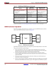
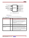
DSOCM-to-BRAM Interfaces
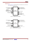
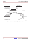
Figure 3-4 provides an example of a basic DSOCM-to-BRAM interface for Virtex-II Pro.
Virtex-II Pro supports only fixed latency connections such as the one shown.
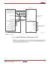
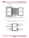
Figure 3-5 shows an example of a basic DSOCM-to-BRAM interface for Virtex-4. Notice
that in fixed latency mode, the output DSOCMRDADDRVALID and
DSOCMWRADDRVALID can be left unconnected.
Note: Individual byte enables in a Virtex-II Pro device require a minimum of four BRAMs for
DSOCM (each BRAM port has a single write enable which is used as byte enable). In a Virtex-4
device, a single BRAM is sufficient, since it can be configured to have individual (that is, four) byte
enables in its 32-bit data configuration.
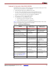
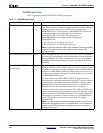
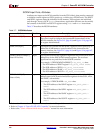
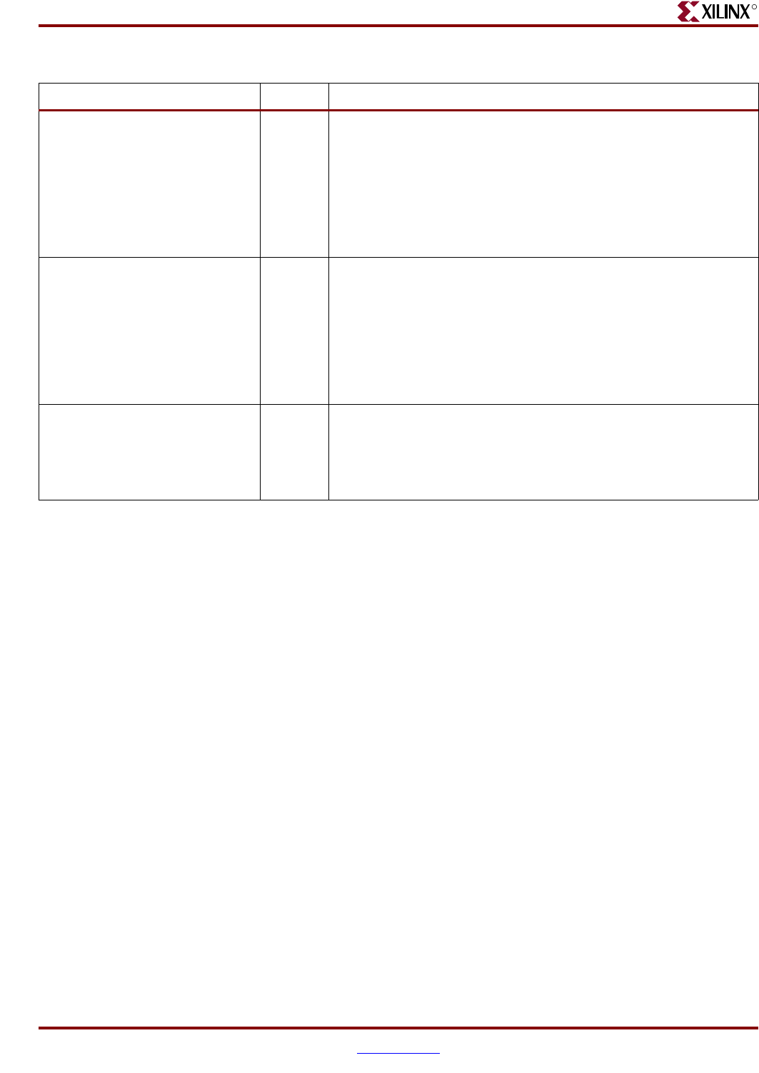
DSOCMRDADDRVALID
(Virtex-4 only)
Output This signal is used when the DSOCM controller is connected to the
logic in the FPGA fabric (e.g. memory-mapped peripheral) with a
variable latency. The signal indicates a read access and indicates
the read address is valid on the DSOCMBRAMABUS[8:29]. This
signal will be asserted for one BRAMDSOCMCLK cycle only. A
memory-mapped slave design should register this signal, as well
as the read address (DSOCMBRAMABUS[8:29]), if the read
operation cannot be completed in the next cycle.
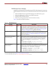
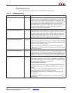
DSOCMWRADDRVALID
(Virtex-4 only)
Output This signal is used when the DSOCM controller is connected to the
logic in the FPGA fabric (e.g., memory-mapped peripheral) with a
variable latency. The signal indicates a write access and indicates
the write address is valid on the DSOCMBRAMABUS[8:29]. This
signal is asserted for one BRAMDSOCMCLK cycle only. A
memory-mapped slave design should register this signal, as well
as the read address (DSOCMBRAMABUS[8:29]) if the read
operation cannot be completed in the next cycle.
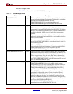
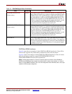
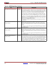
DSOCMBUSY Output This control signal reflects the value of the DSOCM DCR control
register DSCNTL[2] bit output to the FPGA fabric. This signal can
be used for applications that require a software control mechanism
to toggle a control bit to FPGA hardware. It is an optional signal
and need not be used.
Table 3-5: DSOCM Output Ports (Continued)
Port Direction Description