


PowerPC™ 405 Processor Block Reference Guide www.xilinx.com 171
UG018 (v2.0) August 20, 2004 1-800-255-7778
R
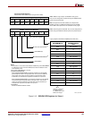
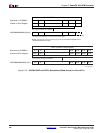
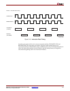
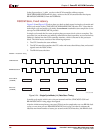
In multi-cycle mode, initial wait cycles are inserted until the CPMC405CLOCK and
BRAMISOCMCLK rising edges are aligned. After the initial startup latency, two
instructions (64 bits) can be fetched every two BRAM clock cycles. If a branch instruction is
taken, the instruction pipeline must be flushed, and the startup latency will again be
encountered beginning with a new instruction address.
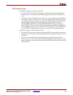
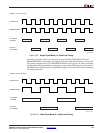
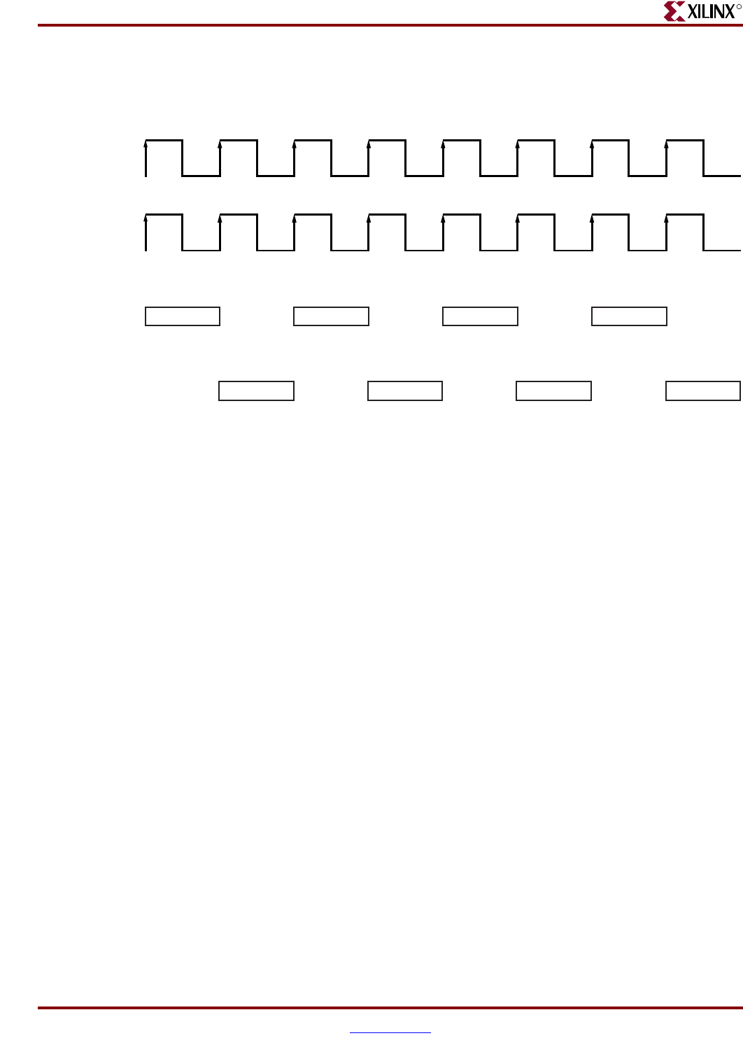
Figure 3-18: Instruction Fetch Timing
UG018_60_03060
3
C
PMC405Clock
I
SOCM 1:1 Instruction Fetch Timing
B
RAMISOCMCLK
L
oad Address
(
To BRAM)
R
ead Data
(
From BRAM)
L_addr_1 L_addr_2 L_addr_3 L_addr_4
Rd_data_1 Rd_data_2 Rd_data_3 Rd_data_4