


110 www.xilinx.com PowerPC™ 405 Processor Block Reference Guide
1-800-255-7778 UG018 (v2.0) August 20, 2004
Chapter 2: Input/Output Interfaces
R
interrupts ahead of noncritical interrupts when they occur simultaneously (certain debug
exceptions are handled at a lower priority). Critical interrupts use a different save/restore
register pair (SRR2 and SRR3) than is used by noncritical interrupts (SRR0 and SRR1). This
enables a critical interrupt to interrupt a noncritical-interrupt handler. The state saved by
the noncritical interrupt is not overwritten by the critical interrupt. See the <RD Red><EM
EmphasisItalic>PowerPC Processor Reference Guide for more information on exception and
interrupt processing.
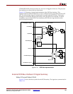
Logic external to the processor block can be used to cause critical and noncritical
interrupts. External interrupt sources are collected by the external interrupt controller
(EIC) and presented to the processor block as either a critical or noncritical interrupt. Once
an external interrupt request is asserted, the EIC must keep the signal asserted until
software deasserts it. This is typically done by writing to a DCR in the EIC peripheral logic.
Software can enable and disable external interrupts using the following bits in the
machine-state register MSR:
x Noncritical interrupts are controlled by MSR[EE]. When set to 1, noncritical interrupts
are enabled. When cleared to 0, they are disabled.
x Critical interrupts are controlled by MSR[CE]. When set to 1, critical interrupts are
enabled. When cleared to 0, they are disabled.
The states of the EE and CE bits are reflected by output signals on the processor block CPM
interface. See “Clock and Power Management Interface,” page 35, for more information.
An external interrupt is considered pending if it occurs while the corresponding class is
disabled. The EIC continues to assert the interrupt request. When software later enables
the interrupt class, the interrupt occurs and the interrupt handler deasserts the request by
writing to a DCR in the EIC.
EIC Interface I/O Signal Summary
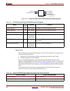
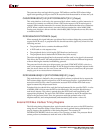
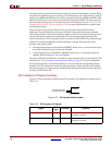
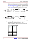
Figure 2-37 shows the block symbol for the EIC interface. The signals are summarized in
Table 2-23.
Figure 2-37: EIC Interface Block Symbol
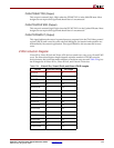
Table 2-23: EIC Interface I/O Signals
Signal
I/O
Type
If Unused Function
EICC405CRITINPUTIRQ I 0 Indicates an external critical
interrupt occurred.
EICC405EXTINPUTIRQ I 0 Indicates an external noncritical
interrupt occurred.
UG018_07_102001
PPC405
EICC405CRITINPUTIRQ
EICC405EXTINPUTIRQ