


164 www.xilinx.com PowerPC™ 405 Processor Block Reference Guide
1-800-255-7778 UG018 (v2.0) August 20, 2004
Chapter 3: PowerPC 405 OCM Controller
R
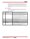
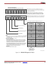
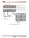
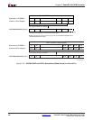
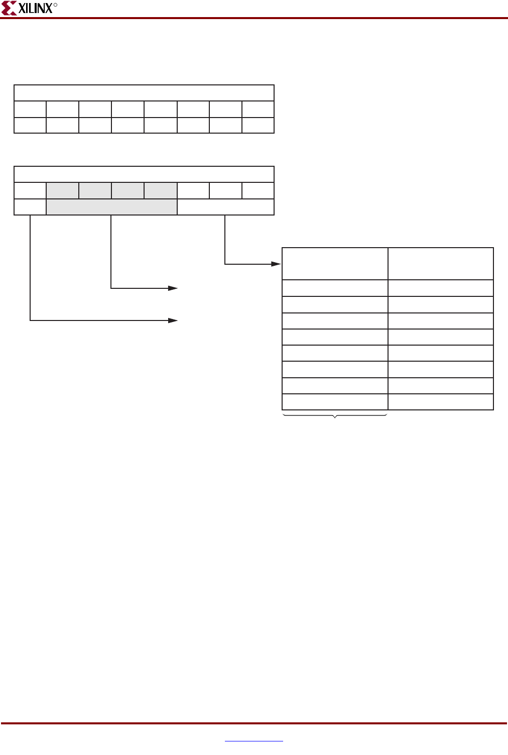
Figure 3-13: ISOCM DCR Registers for Virtex-II Pro
UG018_47_04230
4
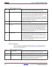
ISARC (ISOCM Address Range Compare Register)
User Programmable Registers
Allocated within DCR address space (Programmer's Model)
8 bits: Address range compare for ISOCM memory space.
They are also configurable via FPGA, through the ISARCVALUE
inputs to the processor block.
Note: The top 8 bits of the CPU address are compared with
ISARC to provide a 16 MB logical address space for ISOCM
block. OCM must be placed in a non-cacheable memory region.
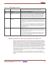
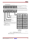
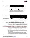
Notes:
1. Reserved bits; will read 0.
2. ISOCMEN:
Enables the ISOCM address decoder.
0
A0/P
1
A1/P
5
A5/P
6
A6/P
7
A7/P
2
A2/P
3
A3/P
4
A4/P
ISCNTL (ISOCM Control Register)
8 bits: Control Register for ISOCM. They are also configurable v
ia
FPGA, through the ISCNTLVALUE inputs to the processor block
.
0
D0/P
1
D1/P...
5
D5/P...
67
D7/P
2 34
D4/P
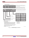
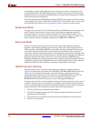
ISOCMMCM[0:2]
ISOCMEN
(2)
000
001
010
011
100
101
110
111
2n - 1
N/A
1:1
N/A
2:1
N/A
3:1
N/A
4:1
CPMC405CLOCK:
BRAMISOCMCLK
Ratio
where n = number of
processor clocks in
one OCM clock cycle.
Must be an integer.
Reserved
(1)
(P indicates that this bit can be configured during FPGA power u
p)