


PowerPC™ 405 Processor Block Reference Guide www.xilinx.com 55
UG018 (v2.0) August 20, 2004 1-800-255-7778
R
PLBC405ICUADDRACK (Input)
When asserted, this signal indicates the PLB slave acknowledges the ICU fetch request
(indicated by the ICU assertion of C405PLBICUREQUEST). When deasserted, no such
acknowledgement exists. A fetch request can be acknowledged by the PLB slave in the
same cycle the request is asserted by the ICU. The PLB slave must latch the following fetch-
request information in the same cycle it asserts the fetch acknowledgement:
x C405PLBICUABUS[0:29], which contains the word address of the instruction-fetch
request.
x C405PLBICUSIZE[2:3], which indicates the instruction-fetch line-transfer size.
x C405PLBICUCACHEABLE, which indicates whether the instruction-fetch address is
cacheable.
x C405PLBICUU0ATTR, which indicates the value of the user-defined storage attribute
for the instruction-fetch address. (Use of this signal is optional.)
During the acknowledgement cycle, the PLB slave must return its bus width indicator (32
bits or 64 bits) using the PLBC405ICUSSIZE1 signal.
The acknowledgement signal remains asserted for one cycle. In the next cycle, both the
fetch request and acknowledgement are deasserted. Instructions can be returned to the
ICU from the PLB slave beginning in the cycle following the acknowledgement. The PLB
slave must abort an ICU fetch request (return no instructions) if the ICU asserts
C405PLBICUABORT in the same cycle the PLB slave acknowledges the request.
The ICU supports two outstanding fetch requests over the PLB. The ICU can make a
second fetch request after the current request is acknowledged. The ICU deasserts
C405PLBICUREQUEST for at least one cycle after the current request is acknowledged and
before the subsequent request is asserted.
If the PLB slave supports address pipelining, it must respond to the two fetch requests in
the order they are presented by the ICU. All instructions associated with the first request
must be returned before any instruction associated with the second request is returned.
The ICU cannot present a third fetch request until the first request is completed by the PLB
slave. This third request can be presented two cycles after the last read acknowledge
(PLBC405ICURDDACK) is sent from the PLB slave to the ICU, completing the first
request.
PLBC405ICUSSIZE1 (Input)
This signal indicates the bus width (size) of the PLB slave device that acknowledged the
ICU fetch request. A 32-bit PLB slave responded when the signal is deasserted (0). A 64-bit
PLB slave responded when the signal is asserted (1). This signal is valid during the cycle
the acknowledge signal (PLBC405ICUADDRACK) is asserted.
The size signal is used by the ICU to determine how instructions are read from the 64-bit
PLB interface during a transfer cycle (a transfer occurs when the PLB slave asserts
PLBC405ICURDDACK). The ICU uses the size signal as follows:
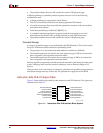
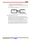
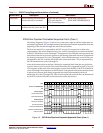
x When a 32-bit PLB slave responds, an aligned word is sent from the slave to the ICU
during each transfer cycle. The 32-bit PLB slave bus should be connected to both the
high and low 32 bits of the 64-bit ICU read-data bus (see Figure 2-5). This type of
connection duplicates the word returned by the slave across the 64-bit bus. The ICU
reads either the low 32 bits or the high 32 bits of the 64-bit interface, depending on the
order of the transfer (PLBC405ICURDWDADDR[1:3]).