


PowerPC™ 405 Processor Block Reference Guide www.xilinx.com 143
UG018 (v2.0) August 20, 2004 1-800-255-7778
R
up with the value on the input ports: DSARCVALUE[0:7] and ISARCVALUE[0:7]
respectively. The two registers can also be loaded using DCR write assembly
instructions (mtdcr).
The value of DSARC and ISARC defines the most significant eight address bits for the
two 16 MB memory spaces (instruction and data) available on the OCM, assuming
OCM address decoding is enabled in bit 0 of the ISCNTL/DSCNTL registers.
Notice that the instruction-side and data-side OCM interfaces can reside in the same 16
MB space or dedicate two 16 MB spaces, i.e., DSARCVALUE[0:7] and
ISARCVALUE[0:7] can be the same value, or they can be different values. However,
once the 16 MB space(s) is defined for instruction-side and data-side OCMs, PLB/OPB
memory spaces cannot overlap with the OCM space(s). For more details, refer to the
“Programmer's Model” section later in this chapter.
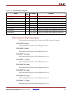
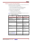
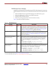
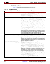
OCM DCR-Based Control Registers (Accessed Via DCR Instructions)
There are two registers (DSARC and DSCNTL) in the DSOCM and four registers (ISARC,
ISCNTL, ISINIT and ISFILL) in the ISOCM.
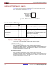
The DSARC/ISARC, DSCNTL/ISCNTL control registers, must be initialized before using
DSOCM/ISOCM interfaces, which also means load and store data via DSOCM and
fetching instructions to the instruction side interface. There are two ways to initialize these
registers:
1. Use DCR assembly instructions (mtdcr, mfdcr) to access all six OCM control registers.
The DCR address for these registers are summarized under the heading “Device-
Control Register Interfaces” in Chapter 2.
2. Specify the associated input ports of the processor block. The values that tie to the 8-bit
input ports DSARCVALUE[0:7], DSCNTLVALUE[0:7] will be the initial value of
DSARC and DSCNTL registers after power on. Similarly, the values that tie to the 8bit
input ports ISARCVALUE[0:7], ISCNTLVALUE[0:7] will be the initial value of ISARC
and ISCNTL registers after power on. Notice that if the processor system will be boot
from the ISOCM memory, the ISARC and ISCNTL registers must be initialized using
this method.
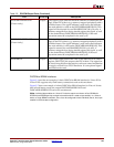
The ISINIT and ISFILL registers are used for content initialization of the instruction side of
OCM memory and for software debugging purposes.
x In Virtex-II Pro: allows the processor to write instructions into the ISOCM memory
array during system initialization, using the ISINIT and the ISFILL registers.
x In Virtex-4: allows the processor to write instructions and read instructions from the
ISOCM memory array using the ISINIT and the ISFILL registers.
More information regarding the functionality of these OCM control registers will be
described in the “Programmer's Model” section of this chapter.
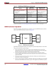
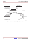
DSOCM Controller Load/Store Operation
The DSOCM controller accepts an address and associated control signals from the
processor during a load instruction, and passes a valid address to the DSOCM's FPGA
fabric or BRAM interface. For store instructions, a valid address from the processor is
accompanied by store data and by the associated control signals. The DSOCM controller
performs an address decode on the eight most significant processor address bits to
determine if the load/store instruction is for the data-side OCM interface. The DSARC