


PowerPC™ 405 Processor Block Reference Guide www.xilinx.com 141
UG018 (v2.0) August 20, 2004 1-800-255-7778
R
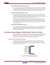
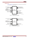
Features for Instruction-Side OCM (ISOCM)
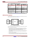
The ISOCM interface contains a 64-bit read only port for instruction fetches and a 32-bit
read and write port to initialize or test the ISBRAM.
x 64-bit Data Read Only bus (two BRAM clock cycles)
x For Virtex-II Pro, 32-bit Data Write Only bus through DCR instruction.
For Virtex-4, 32-bit Data Read and Write bus through DCR instruction.
x Separate 21-bit read only and write only addresses to ISBRAM.
x DCR registers: ISCNTL, ISARC, ISINIT, ISFILL.
x Two alternatives to setup ISBRAM contents:
i Use DCR to access the 32-bit Data write bus.
i Initialize ISBRAM during FPGA configuration.
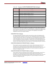
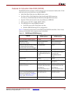
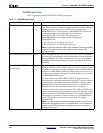
Table 3-2 summarizes the features of the DSOCM and ISOCM controllers. Virtex-4 only
features are identified with a separate entry in the table.
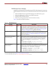
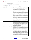
Table 3-2: DSOCM and ISOCM Features
Feature
Data-Side
OCM Interface
Instruction-Side
OCM Interface
Non-cacheable memory space. 16 MB 16 MB
Data bus width
(load/store/fetch).
32-bit bi-directional
(load/store)
64-bit unidirectional
(Instruction fetch)
Data bus width (DCR read/write)
for instruction side memory
interface and software debugger.
Not applicable 32-bit
a
Byte write support.
Yes Not applicable
Maximum performance.
One load/store for every
two BRAMDSOCMCLK
cycles
Two instruction fetches
for every two
BRAMISOCMCLK
cycles
Address bus.
22 bits 21 bits
DCR control registers.
DSARC and DSCNTL ISARC, ISCNTL, ISINIT,
and ISFILL
OCM DCR control register base
address selection.
For Virtex-II Pro:
TIEDSOCMDCRADDR
For Virtex-4:
TIEDCRADDR+offset
b
For Virtex-II Pro:
TIEISOCMDCRADDR
For Virtex-4:
TIEDCRADDR+offset
b
Default settings applied at
power up through dedicated
processor inputs (see “DSOCM
Ports” and “ISOCM Ports”).
DSARCVALUE and
DSCNTLVALUE
ISARCVALUE and
ISCNTLVALUE
OCM Clock. BRAMDSOCMCLK BRAMISOCMCLK