


PowerPC™ 405 Processor Block Reference Guide www.xilinx.com 81
UG018 (v2.0) August 20, 2004 1-800-255-7778
R
must abort a DCU request (move no data) if the DCU asserts C405PLBDCUABORT in the
same cycle the PLB slave acknowledges the request.
The DCU supports up to three outstanding requests over the PLB (two read and one write).
The DCU can make a subsequent request after the current request is acknowledged. The
DCU deasserts C405PLBDCUREQUEST for at least one cycle after the current request is
acknowledged and before the subsequent request is asserted.
If the PLB slave supports address pipelining, it must respond to multiple requests in the
order they are presented by the DCU. All data associated with a prior request must be
moved before data associated with a subsequent request is accessed. The DCU cannot
present a third read request until the first read request is completed by the PLB slave, or a
second write request until the first write request is completed. Such a request (third read or
second write) can be presented two cycles after the last acknowledge is sent from the PLB
slave to the DCU, completing the first request (read or write, respectively).
PLBC405DCUSSIZE1 (Input)
This signal indicates the bus width (size) of the PLB slave device that acknowledged the
DCU request. A 32-bit PLB slave responded when the signal is deasserted (0). A 64-bit PLB
slave responded when the signal is asserted (1). This signal is valid during the cycle the
acknowledge signal (PLBC405DCUADDRACK) is asserted.
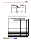
A 32-bit PLB slave must be attached to a 64-bit PLB master, as shown in Figure 2-16,
page 77. In this figure, the 32-bit read-data bus from the PLB slave is attached to both the
high word and low word of the 64-bit read-data bus at the PLB master. The 32-bit write-
data bus into the PLB slave is attached to the high word of the 64-bit write-data bus at the
PLB master. The low word of the 64-bit write-data bus is not connected. When a 64-bit PLB
master recognizes a 32-bit PLB slave (the size signal is deasserted), data transfers operate
as follows:
x During a single word read, data is received by the 64-bit master over the high word
(bits 0:31) or the low word (bits 32:63) of the read-data bus as specified by the byte
enable signals.
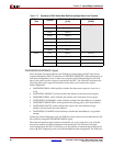
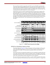
x During an eight-word line read, data is received by the 64-bit master over the high
word (bits 0:31) or the low word (bits 32:63) of the read-data bus as specified by bit 3
of the transfer order (PLBC405DCURDWDADDR[1:3]). Table 2-10, page 58, shows the
location of data on the DCU read-data bus as a function of transfer order when an
eight-word line read from a 32-bit PLB slave occurs.
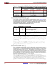
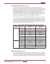
x During a single word write or an eight-word line write, data is sent by the 64-bit
master over the high word (bits 0:31) of the write-data bus. Table 2-15, page 80, shows
the order data is transferred to a 32-bit PLB slave during an eight-word line write.
All bits of the read-data bus and write-data bus are directly connected between a 64-bit
PLB slave and a 64-bit PLB master. When a 64-bit PLB master recognizes a 64-bit PLB slave
(the size signal is asserted), data transfers operate as follows:
x During a single word read, data is received by the 64-bit master over the high word
(bits 0:31) or the low word (bits 32:63) of the read-data bus as specified by the byte
enable signals.
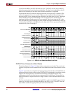
x During an eight-word line read, data is received by the 64-bit master over the entire
read-data bus. Table 2-10, page 58, shows the location of data on the DCU read-data
bus as a function of transfer order when an eight-word line read from a 64-bit PLB
slave occurs.