


34 www.xilinx.com PowerPC™ 405 Processor Block Reference Guide
1-800-255-7778 UG018 (v2.0) August 20, 2004
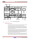
Chapter 2: Input/Output Interfaces
R
Appendix B, “Signal Summary,” alphabetically lists the signals described in this chapter.
The l/O designation and a description summary are included for each signal.
Signal Naming Conventions
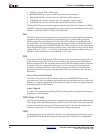
The following convention is used for signal names throughout this document:
PREFIX1PREFIX2SIGNAME1[SIGNAME2][NEG][(m:n)]
The components of a signal name are as follows:
x PREFIX1 is an uppercase prefix identifying the source of the signal. This prefix
specifies either a unit (for example, CPU) or a type of interface (for example, DCR). If
PREFIX1 specifies the processor block, the signal is considered an output signal.
Otherwise, it is an input signal.
x PREFIX2 is an uppercase prefix identifying the destination of the signal. This prefix
specifies either a unit (for example, CPU) or a type of interface (for example, DCR). If
PREFIX2 specifies the processor block, the signal is considered an input signal.
Otherwise, it is an output signal.
x SIGNAME1 is an uppercase name identifying the primary function of the signal.
x SIGNAME2 is an uppercase name identifying the secondary function of the signal.
x [NEG] is an optional notation that indicates a signal is active low. If this notation is not
use, the signal is active high.
x [m:n] is an optional notation that indicates a bussed signal. “m” designates the most-
significant bit of the bus and “n” designates the least-significant bit of the bus.
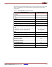
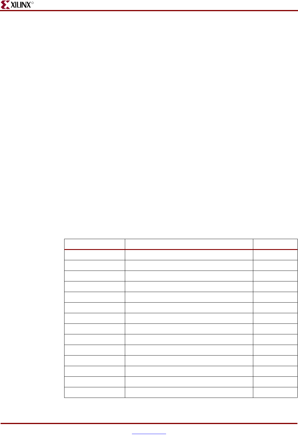
Table 2-1 defines the prefixes used in the signal names. The “Location” column in the table
identifies whether the functional unit resides inside or outside the processor block.
Table 2-1: Signal Name Prefix Definitions
Prefix1 or Prefix2 Definition Location
CPM Clock and power management Outside
C405 Processor block Inside
DBG Debug unit Inside
DCR Device control register Outside
DSOCM Data-side on-chip memory (DSOCM) Outside
a
EIC External interrupt controller Outside
ISOCM Instruction-side on-chip memory (ISOCM) Outside
a
JTG JTAG Inside
PLB Processor local bus Inside
RST Reset Inside
TIE TIE (signal tied statically to GND or V
DD
)Outside
TRC Trace Inside
APU Auxiliary Processor Unit Controller Inside
FCM Fabric Co-Processor Module Outside