PowerPC™ 405 Processor Block Reference Guide www.xilinx.com 147
UG018 (v2.0) August 20, 2004 1-800-255-7778
R
DSOCM Input Ports: Attributes
Attributes are inputs to the OCM controller from the FPGA fabric that must be connected to
initialize registers at FPGA power up, or following a processor reset. These inputs are used
to:
x Define the DSOCM control register DCR addresses in the DCR memory space.
x Define the 16MB memory locations for the DSOCM controller.
x Enable the DSOCM address decoder.
x Define the operating characteristics for the bus interface circuitry.
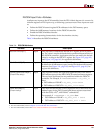
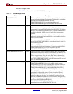
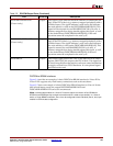
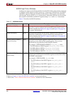
Table 3-4 describes the DSOCM attributes.
Table 3-4: DSOCM Attributes
Attribute Direction Description
DSCNTLVALUE[0:7] Input This input bus is loaded into the DSCNTL register at FPGA power-
up. The value is used to define the basic operational characteristics of
the DSOCM controller. Application software can modify the default
value by writing to the DSCNTL register. See Figure 3-11, page 162,
and Figure 3-12, page 163, for register bit definitions.
DSARCVALUE[0:7] Input This input bus is loaded into the DSARC register at FPGA power up.
It defines the 16 MB memory space location for the data-side memory
interface. See Figure 3-11, page 162, and Figure 3-12, page 163, for
register bit definitions.
TIEDSOCMDCRADDR[0:7]
(Virtex-II Pro only)
a
Input This input bus defines the eight most significant bits of the ten-bit
DCR address space for the DSOCM DCR control and status registers.
The two least significant bits are predefined within the DSOCM
controller. For example, if TIEDSOCMDCRADDR = 00_0001_11
then:
x DCR address of DSARC = 00_0001_1110 = 0x01E
x DCR address of DSCNTL = 00_0001_1111 = 0x01F
TIEDCRADDR[0:5]
(Virtex-4 only)
a
Input This input bus defines the six most significant bits of the ten-bit DCR
address space for the DCR Control and Status registers associated
with the OCM, APU
b
, AND EMAC
c
submodules.
For example, if TIEDCRADDR = 00_0001 then:
x DCR address of DSARC = 00_0001_0110 = 0x016
x DCR address of DSCNTL = 00_0001_0111 = 0x017
a. For more information, refer to the “Device-Control Register Interfaces” section in Chapter 2.
b. For more information, refer to Chapter 4, “PowerPC 405 APU Controller”.
c. For more information, refer to the Virtex-4 Ethernet Media Access Controller manual.


