


128 www.xilinx.com PowerPC™ 405 Processor Block Reference Guide
1-800-255-7778 UG018 (v2.0) August 20, 2004
Chapter 2: Input/Output Interfaces
R
.JTGC405BNDSCANTDO (),
.C405JTGTDOEN (TDO_TS_OUT2),
.C405JTGEXTEST (),
.C405JTGCAPTUREDR (),
.C405JTGSHIFTDR (),
.C405JTGUPDATEDR (),
.C405JTGPGMOUT (),
...
);
JTAGPPC U_JTAG(
TDOTSPPC (TDO_TS_PPC),
TDOPPC (TDO_OUT2),
TMS (TMS_PPC),
TDIPPC (TDI_PPC),
TCK (TCK_PPC)
);
endmodule;
Debug Interface
The debug interface enables an external debugging tool (such as RISCWatch) to operate the
PowerPC 405 debug resources in external-debug mode. External-debug mode can be used
to alter normal program execution and it provides the ability to debug system hardware as
well as software. The mode supports starting and stopping the processor, single-stepping
instruction execution, setting breakpoints, and monitoring processor status. These
capabilities are described in the PowerPC Processor Reference Guide.
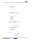
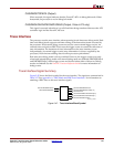
Debug Interface I/O Signal Summary
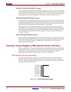
Figure 2-46 shows the block symbol for the debug interface. The signals are summarized in
Table 2-26. See Appendix A, “RISCWatch and RISCTrace Interfaces” for information on
attaching a RISCWatch to the debug interface signals.
Figure 2-46: Debug Interface Block Symbol
PPC405
DBGC405EXTBUSHOLDACK
DBGC405DEBUGHALT
DBGC405UNCONDDEBUGEVENT
C405DBGWBFULL
C405DBGWBIAR[0:29]
C405DBGWBCOMPLETE
C405DBGMSRWE
C405DBGSTOPACK
C405DBGLOADDATAONAPUDBUS
UG018_02_46_042304