


134 www.xilinx.com PowerPC™ 405 Processor Block Reference Guide
1-800-255-7778 UG018 (v2.0) August 20, 2004
Chapter 2: Input/Output Interfaces
R
C405TRCTRACESTATUS[0:3] (Output)
These signals provide additional information required by a trace tool when reconstructing
an instruction execution sequence. This information is collected every processor cycle, but
it is made available to the trace interface once every two cycles. The information collected
during those two cycles is broadcast over the trace interface in a single trace cycle.
TRCC405TRIGGEREVENTIN (Input)
When asserted, this signal indicates that a trigger event occurred. The PowerPC 405 uses
this signal to generate additional information that is output on the trace-status bus. This
information corresponds to the execution status produced on the even and odd execution-
status busses. When deasserted, the information is not generated.
This signal can be produced by FPGA logic using the trigger event output signal. The
output signal can be combined with the trigger event-type signals before it is returned as
the input signal. This capability can be used to implement various trace collection schemes.
The external trace tool should monitor the trigger-event input signal to synchronize its
own trace collection.
TRCC405TRACEDISABLE (Input)
When asserted, this signal disables the collection and broadcast of trace information. Trace
information already collected by the processor when this signal is asserted is broadcast on
the trace interface before tracing is disabled. When deasserted, trace collection and
broadcast proceed normally.
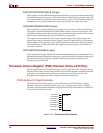
Processor Version Register (PVR) Interface (Virtex-4-FX Only)
The PowerPC block in Virtex-4 provides user access to eight bits in the Processor Version
Register (PVR) in the processor. One possible use for these tie signals is to identify different
processors in a multi processor system or to encode some processor environment
description allowing generic code to adapt its execution on that basis.
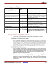
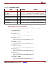
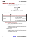
PVR Interface I/O Signal Summary
The PVR provides software access to a five field 32-bit value. The fields are: Owner
Identifier, Processor Core Family, Cache Array size, Processor core version, and FPGA
identifier. The least significant nibbles of the Owner and FPGA identifier are available on
the PowerPC interface as tie-offs.
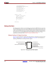
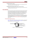
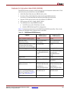
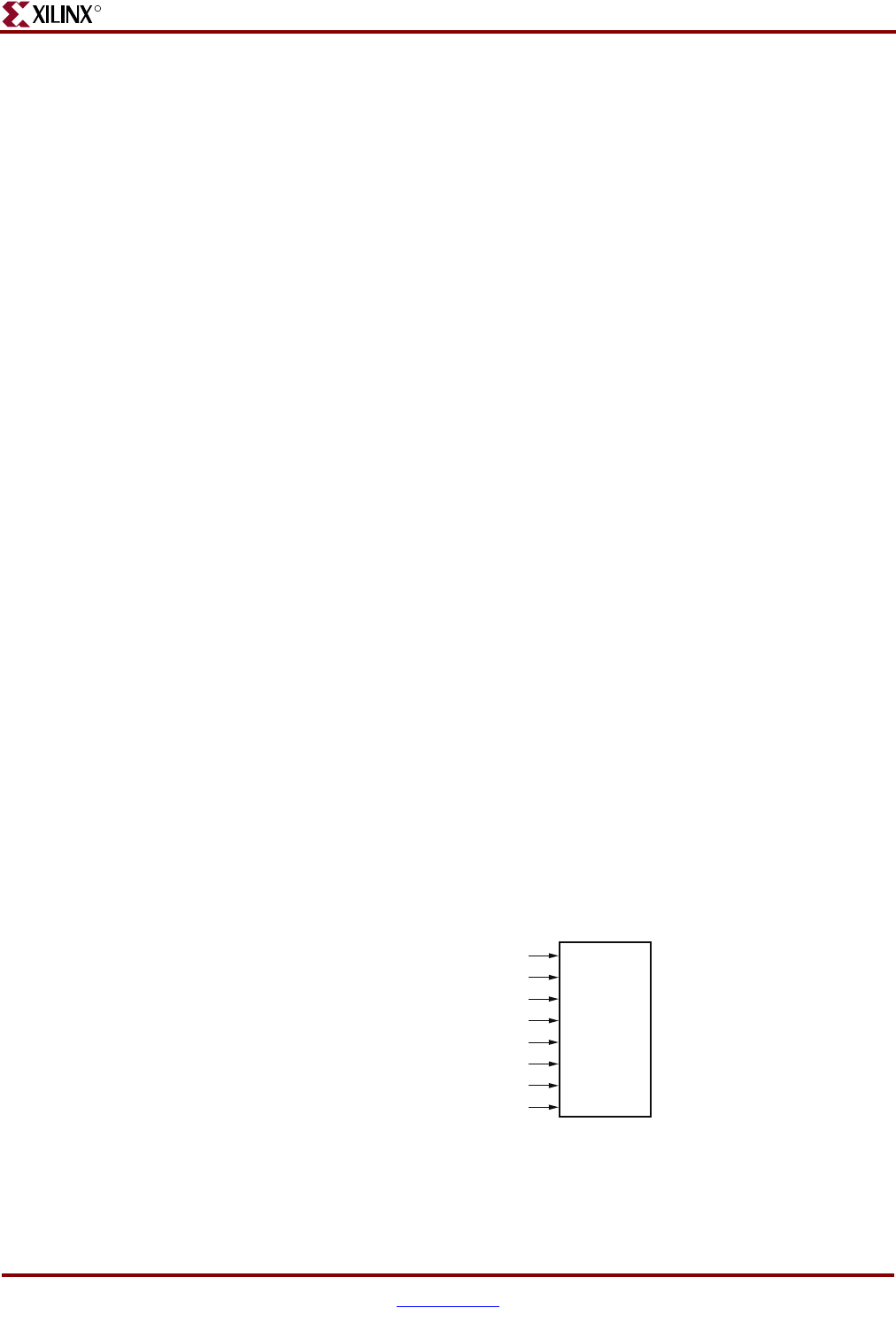
Figure 2-48: PVR Interface Block Symbol
PPC405
TIEPVRBIT8
TIEPVRBIT9
TIEPVRBIT10
TIEPVRBIT11
TIEPVRBIT28
TIEPVRBIT29
TIEPVRBIT30
TIEPVRBIT31
UG018_02_48_032504