


216 www.xilinx.com PowerPC™ 405 Processor Block Reference Guide
1-800-255-7778 UG018 (v2.0) August 20, 2004
Appendix B: Signal Summary
R
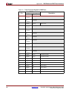
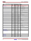
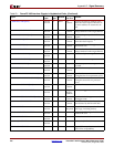
C405PLBICUABUS[0:29] V-II Pro
and V-4
OISPLBNo
Connect
Specifies the memory address of the
instruction-fetch request. Bits 30:31 of
the 32-bit address are assumed to be
zero.
C405PLBICUCACHEABLE V-II Pro
and V-4
OISPLBNo
Connect
Indicates the value of the cacheability
storage attribute for the target address.
C405PLBICUPRIORITY[0:1] V-II Pro
and V-4
OISPLBNo
Connect
Indicates the priority of the ICU fetch
request.
C405PLBICUREQUEST V-II Pro
and V-4
OISPLBNo
Connect
Indicates the ICU is making an
instruction-fetch request.
C405PLBICUSIZE[2:3] V-II Pro
and V-4
OISPLBNo
Connect
Specifies a four word or eight word
line-transfer size.
C405PLBICUU0ATTR V-II Pro
and V-4
OISPLBNo
Connect
Indicates the value of the user-defined
storage attribute for the target address.
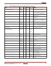
C405RSTCHIPRESETREQ V-II Pro
and V-4
O Reset Required Indicates a chip-reset request occurred.
C405RSTCORERESETREQ V-II Pro
and V-4
O Reset Required Indicates a core-reset request occurred.
C405RSTSYSRESETREQ V-II Pro
and V-4
O Reset Required Indicates a system-reset request
occurred.
C405TRCCYCLE V-II Pro
and V-4
OTrace No
Connect
Specifies the trace cycle.
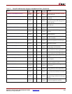
C405TRCEVENEXECUTIONSTATUS[0:1] V-II Pro
and V-4
OTrace No
Connect
Specifies the execution status collected
during the first of two processor cycles.
C405TRCODDEXECUTIONSTATUS[0:1] V-II Pro
and V-4
OTrace No
Connect
Specifies the execution status collected
during the second of two processor
cycles.
C405TRCTRACESTATUS[0:3] V-II Pro
and V-4
OTrace No
Connect
Specifies the trace status.
C405TRCTRIGGEREVENTOUT V-II Pro
and V-4
OTrace Wrap to
Trigger
Event In
Indicates a trigger event occurred.
C405TRCTRIGGEREVENTTYPE[0:10] V-II Pro
and V-4
OTrace No
Connect
Specifies which debug event caused
the trigger event.
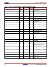
C405XXXMACHINECHECK V-II Pro
and V-4
O Control No
Connect
Indicates a machine-check error has
been detected by the PowerPC 405.
CPMC405CLOCK V-II Pro
and V-4
ICPM1
Required
PowerPC 405 clock input (for all non-
JTAG logic, including timers).
CPMC405CORECLKINACTIVE V-II Pro
and V-4
I CPM 0 Indicates the CPM logic disabled the
clocks to the core.
CPMC405CPUCLKEN V-II Pro
and V-4
I CPM 1 Enables the core clock zone.
CPMC405JTAGCLKEN V-II Pro
and V-4
I CPM 1 Enables the JTAG clock zone.
CPMC405SYNCBYPASS V-4 I CPM 1 Bypass PLB re-synchronization for
Virtex-II Pro compatibility.
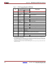
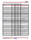
Table B-1: PowerPC 405 Interface Signals in Alphabetical Order (Continued)
Signal
FPGA
Type
a
I/O
Type
Interface
If Unused
Ties To:
b
Function