


28 www.xilinx.com PowerPC™ 405 Processor Block Reference Guide
1-800-255-7778 UG018 (v2.0) August 20, 2004
Chapter 1: Introduction to the PowerPC 405 Processor
R
Software manages the initialization and replacement of TLB entries. The PowerPC 405
includes instructions for managing TLB entries by software running in privileged mode.
This capability gives significant control to system software over the implementation of a
page replacement strategy. For example, software can reduce the potential for TLB
thrashing or delays associated with TLB-entry replacement by reserving a subset of TLB
entries for globally accessible pages or critical pages.
Storage attributes are provided to control access of memory regions. When memory
translation is enabled, storage attributes are maintained on a page basis and read from the
TLB when a memory access occurs. When memory translation is disabled, storage
attributes are maintained in storage-attribute control registers. A zone-protection register
(ZPR) is provided to allow system software to override the TLB access controls without
requiring the manipulation of individual TLB entries. For example, the ZPR can provide a
simple method for denying read access to certain application programs.
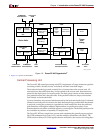
Instruction and Data Caches
The PowerPC 405 accesses memory through the instruction-cache unit (ICU) and data-
cache unit (DCU). Each cache unit includes a PLB-master interface, cache arrays, and a
cache controller. Hits into the instruction cache and data cache appear to the CPU as single-
cycle memory accesses. Cache misses are handled as requests over the PLB bus to another
PLB device, such as an external-memory controller.
The PowerPC 405 implements separate instruction-cache and data-cache arrays. Each is 16
KB in size, is two-way set-associative, and operates using 8 word (32 byte) cache lines. The
caches are non-blocking, allowing the PowerPC 405 to overlap instruction execution with
reads over the PLB (when cache misses occur).
The cache controllers replace cache lines according to a least-recently used (LRU)
replacement policy. When a cache line fill occurs, the most-recently accessed line in the
cache set is retained and the other line is replaced. The cache controller updates the LRU
during a cache line fill.
The ICU supplies up to two instructions every cycle to the fetch and decode unit. The ICU
can also forward instructions to the fetch and decode unit during a cache line fill,
minimizing execution stalls caused by instruction-cache misses. When the ICU is accessed,
four instructions are read from the appropriate cache line and placed temporarily in a line
buffer. Subsequent ICU accesses check this line buffer for the requested instruction prior to
accessing the cache array. This allows the ICU cache array to be accessed as little as once
every four instructions, significantly reducing ICU power consumption.
The DCU can independently process load/store operations and cache-control instructions.
The DCU can also dynamically reprioritize PLB requests to reduce the length of an
execution stall. For example, if the DCU is busy with a low-priority request and a
subsequent storage operation requested by the CPU is stalled, the DCU automatically
increases the priority of the current (low-priority) request. The current request is thus
finished sooner, allowing the DCU to process the stalled request sooner. The DCU can
forward data to the execute unit during a cache line fill, further minimizing execution stalls
caused by data-cache misses.
Additional features allow programmers to tailor data-cache performance to a specific
application. The DCU can function in write-back or write-through mode, as determined by
the storage-control attributes. Loads and stores that do not allocate cache lines can also be
specified. Inhibiting certain cache line fills can reduce potential pipeline stalls and
unwanted external-bus traffic.