


PowerPC™ 405 Processor Block Reference Guide www.xilinx.com 209
UG018 (v2.0) August 20, 2004 1-800-255-7778
R
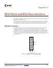
RISCTrace Interface
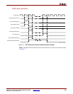
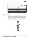
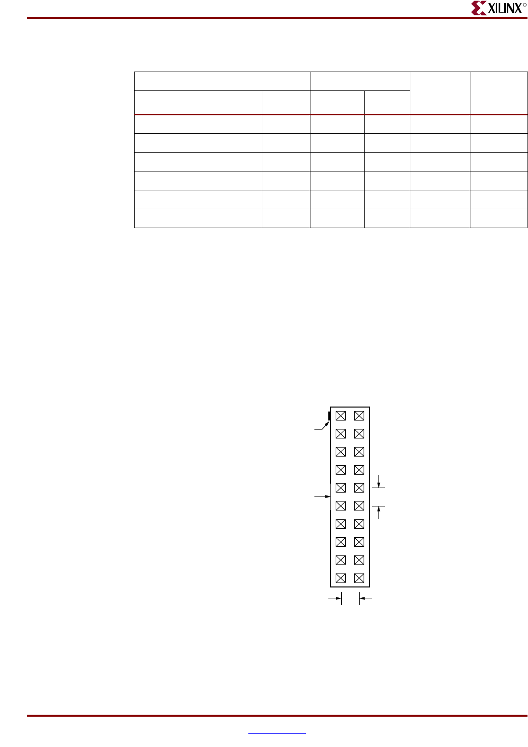
The RISCTrace tool communicates with the PowerPC 405 using the trace interface. It
requires a 20-pin, male 2x10 header connector (3M 3592-6002 or equivalent) located on the
target development board. The layout of the connector is shown in Figure A-2 and the
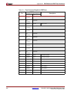
signals are described in Table A-3. A mapping of PowerPC 405 to RISCTrace signals is
provided in Table A-4. At the board level, the connector should be placed as close as
possible to the processor chip to ensure signal integrity. An index at pin one and a key
notch on the same side of the connector as the index are required.
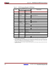
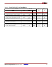
Table A-2: PowerPC 405 to RISCWatch Signal Mapping
PowerPC 405 RISCWatch JTAG
Connector
Pin
Mictor
Connector
Pin
Signal I/O Signal I/O
C405JTGTDO
a
a. This signal must be driven by a tri-state device using C405JTGTDOEN as the enable signal.
Output TDO Input 1 11
JTGC405TDI Input TDI Output 3 19
JTGC405TRSTNEG Input TRST Output 4 21
JTGC405TCK Input TCK Output 7 15
JTGC405TMS Input TMS Output 9 17
DBGC405DEBUGHALT
b2
b. This signal must be inverted between the PowerPC 405 and the RISCWatch.
Input HALT Output 11 7
Figure A-2: Trace-Connector Physical Layout
UG018_51_100901
19 20
1
2
0.1"
0.1"
Key Notch
Index