


PowerPC™ 405 Processor Block Reference Guide www.xilinx.com 41
UG018 (v2.0) August 20, 2004 1-800-255-7778
R
clocks for the OCM controllers in the processor block: BRAMDSOCMCLK (data side
controller) and BRAMISOCMCLK (instruction side controllers).
The data side controller and the instruction side controllers can run at different
frequencies, based upon the access time of the BRAM. When the processor block, OCM
controller, and BRAMs run at the same clock frequency, the processor is in single-cycle
mode. Multi-cycle mode occurs when the processor is running at a higher frequency than
the BRAMs. In the single-cycle mode and multi-cycle mode, the BRAMISOCMCLK and
BRAMDSOCMCLK signals are provided to the OCM controller as inputs.
Through timing analysis, the clock ratio between the processor block clock and the BRAMs
clocks is determined by the worst case access time between the OCM controller interface
and the BRAMs interface. Based upon the timing analysis, most designs use multi-cycle
mode.
The processor block clock and the BRAMDSOCMCLK must be integer multiples. The
same is true for the BRAMISOCMCLK with respect to the processor block clock. They need
not share the same integer values nor integer clock ratio with respect to the PLB clock.
Because the clock ratio between the processor block and the OCM clocks is unknown, the
processor block has control registers in the OCM controllers. The control registers are
ISCNTL[0:7] and DSCNTL[0:7] for the instruction side and data side, respectively. Refer to
Chapter 3, “PowerPC 405 OCM Controller” for more details.
CPU Control Interface
The CPU control interface is used primarily to provide CPU setup information to the
PowerPC 405. It is also used to report the detection of a machine check condition within the
PowerPC 405.
CPU Control Interface I/O Signal Summary
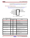
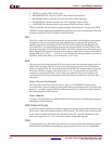
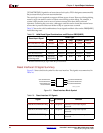
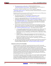
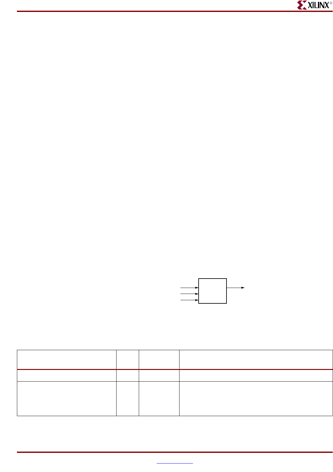
Figure 2-2 shows the block symbol for the CPU control interface. The signals are
summarized in Table 2-3.
Figure 2-2: CPU Control Interface Block Symbol
UG018_02_102001
PPC405
TIEC405MMUEN
TIEC405DETERMINISTICMULT
TIEC405DISOPERANDFWD
C405XXXMACHINECHECK
Table 2-3: CPU Control Interface I/O Signals
Signal
I/O
Type
If Unused Function
TIEC405MMUEN I Required Enables the memory-management unit (MMU).
TIEC405DETERMINISTICMULT I 0
Important: This signal should always be driven low.
Specifies whether all multiply operations complete in
a fixed number of cycles or have an early-out
capability