


54 www.xilinx.com PowerPC™ 405 Processor Block Reference Guide
1-800-255-7778 UG018 (v2.0) August 20, 2004
Chapter 2: Input/Output Interfaces
R
C405PLBICUU0ATTR (Output)
This signal reflects the value of the user-defined (U0) storage attribute for the target
address. The requested instructions are not in memory locations characterized by this
attribute when the signal is deasserted (0). They are in memory locations characterized by
this attribute when the signal is asserted (1). This signal is valid during the time the fetch-
request signal (C405PLBICUREQUEST) is asserted. It remains valid until the cycle
following acknowledgement of the request by the PLB slave (the PLB slave asserts
PLBC405ICUADDRACK to acknowledge the request).
The system designer can use this signal to assign special behavior to certain memory
addresses. Its use is optional.
C405PLBICUABORT (Output)
When asserted, this signal indicates the ICU is aborting the current fetch request. It is used
by the ICU to abort a request that has not been acknowledged, or is in the process of being
acknowledged by the PLB slave. The fetch request continues normally if this signal is not
asserted. This signal is only valid during the time the fetch-request signal
(C405PLBICUREQUEST) is asserted. It must be ignored by the PLB slave if the fetch-
request signal is not asserted. In the cycle after the abort signal is asserted, the fetch-request
signal is deasserted and remains deasserted for at least one cycle.
If the abort signal is asserted in the same cycle that the fetch request is acknowledged by
the PLB slave (PLBC405ICUADDRACK is asserted), the PLB slave is responsible for
ensuring that the transfer does not proceed further. The PLB slave cannot assert the ICU
read-data bus acknowledgement signal (PLBC405ICURDDACK) for an aborted request.
The ICU can abort an address-pipelined fetch request while the PLB slave is responding to
a previous fetch request. The PLB slave is responsible for completing the previous fetch
request and aborting the new (pipelined) request.
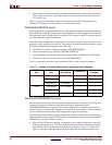
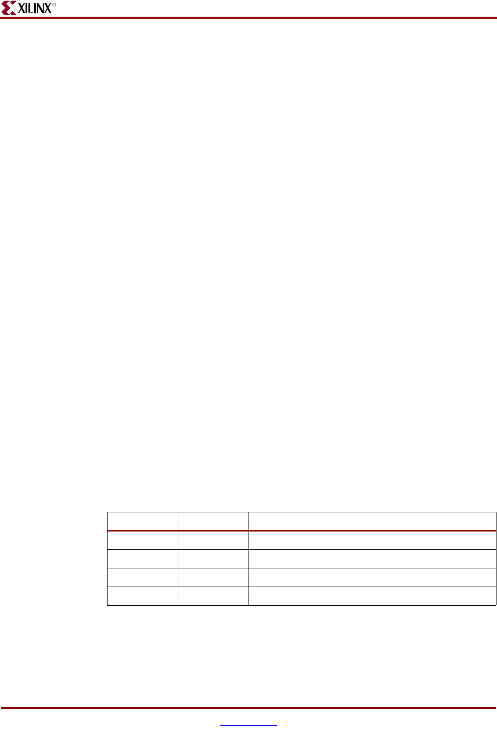
C405PLBICUPRIORITY[0:1] (Output)
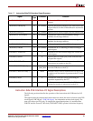
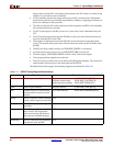
These signals are used to specify the priority of the instruction-fetch request. Table 2-8
shows the encoding of the 2-bit PLB-request priority signal. The priority is valid during the
cycles the fetch-request signal (C405PLBICUREQUEST) is asserted. It remains valid until
the cycle following acknowledgement of the request by the PLB slave. (The PLB slave
asserts PLBC405ICUADDRACK to acknowledge the request.)
Software establishes the instruction-fetch request priority by writing the appropriate value
into the ICU PLB-priority bits 0:1 of the core-configuration register (CCR0[IPP]). After a
reset, the priority is set to the highest level (CCR0[IPP]
0b11).
Table 2-8: PLB-Request Priority Encoding
Bit 0 Bit 1 Definition
0 0 Lowest PLB-request priority.
0 1 Next-to-lowest PLB-request priority.
1 0 Next-to-highest PLB-request priority.
1 1 Highest PLB-request priority.