


82 www.xilinx.com PowerPC™ 405 Processor Block Reference Guide
1-800-255-7778 UG018 (v2.0) August 20, 2004
Chapter 2: Input/Output Interfaces
R
x During a single word write, the DCU replicates the data on the high and low words of
the write data bus. The byte enables indicate which bytes on the high word or low
word are valid and should be latched by the PLB slave.
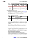
x During an eight-word line write, data is sent by the 64-bit master over the entire
write-data bus. Table 2-15, page 80, shows the order data is transferred to a 64-bit PLB
slave during an eight-word line write. Data is written in order of ascending address,
so the transfer order signals are not used during a line write.
PLBC405DCURDDACK (Input)
When asserted, this signal indicates the DCU read-data bus contains valid data sent by the
PLB slave to the DCU (read data is acknowledged). The DCU latches the data from the bus
at the end of the cycle this signal is asserted. The contents of the DCU read-data bus are not
valid when this signal is deasserted.
Read-data acknowledgement is asserted for one cycle per transfer. There is no limit to the
number of cycles between two transfers. The number of transfers (and the number of read-
data acknowledgements) depends on the PLB slave size (specified by
PLBC405DCUSSIZE1) and the line-transfer size (specified by C405PLBDCUSIZE2). The
number of transfers are summarized as follows:
x Single word reads require one transfer, regardless of the PLB slave size.
x Eight-word line reads require eight transfers when sent from a 32-bit PLB slave.
x Eight-word line reads require four transfers when sent from a 64-bit PLB slave.
PLBC405DCURDDBUS[0:63] (Input)
This read-data bus contains the data transferred from a PLB slave to the DCU. The contents
of the bus are valid when the read-data acknowledgement signal is asserted. This
acknowledgment is asserted for one cycle per transfer. There is no limit to the number of
cycles between two transfers. The bus contents are not valid when the read-data
acknowledgement signal is deasserted.
The PLB slave returns data as an aligned word or an aligned doubleword. This depends on
the PLB slave size (bus width), as follows:
x When a 32-bit PLB slave responds, an aligned word is sent from the slave to the DCU
during each transfer cycle. The 32-bit PLB slave bus should be connected to both the
high and low 32 bits of the 64-bit read-data bus (see Figure 2-16, page 77). This type of
connection duplicates the word returned by the slave across the 64-bit bus. The DCU
reads either the low 32 bits or the high 32 bits of the 64-bit interface, depending on the
value of PLBC405DCURDWDADDR[1:3].
x When a 64-bit PLB slave responds, an aligned doubleword is sent from the slave to the
DCU during each transfer cycle. Both words are read from the 64-bit interface by the
DCU in this cycle.
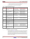
For a single word transfer, the bytes enables are used to select the valid data bytes from the
aligned word or doubleword. Table 2-13, page 77 shows how the byte enables are
interpreted by the processor when reading data during single word transfers from 32-bit
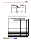
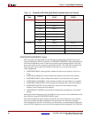
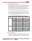
and 64-bit PLB slaves. Table 2-16 shows the location of data on the DCU read-data bus as a
function of PLB-slave size and transfer order when an eight-word line read occurs.