222 www.xilinx.com PowerPC™ 405 Processor Block Reference Guide
1-800-255-7778 UG018 (v2.0) August 20, 2004
Appendix B: Signal Summary
R
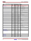
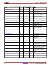
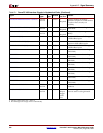
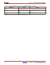
TIEC405DETERMINISTICMULT (INPUT) V-II Pro
and V-4
I Control 0
Required
Specifies whether all multiply
operations complete in a fixed number
of cycles or have an early-out
capability.
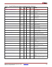
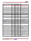
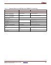
TIEC405DISOPERANDFWD (INPUT) V-II Pro
and V-4
I Control 0
Required
Disables operand forwarding for load
instructions.
TIEC405MMUEN (INPUT) V-II Pro
and V-4
I Control 0
Required
Enables the memory-management unit
(MMU)
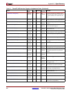
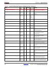
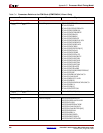
TIEDCRADDR[0:5] V-4 I DCR 0 Location of PPC internal DCR registers
in DCR address space
TIEDSOCMDCRADDR[0:7] V-II Pro I DSOCM 0 Location of PPC DSOCM DCR
registers in DCR address space
TIEISOCMDCRADDR[0:7] V-II Pro I ISOCM 0 Location of PPC ISOCM DCR registers
in DCR address space
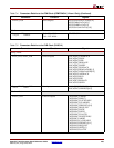
TIEPVRBIT10 V-4 I PVR 0 Set bit 10 in Processor Version Register
(OWN field)
TIEPVRBIT11 V-4 I PVR 0 Set bit 11 in Processor Version Register
(OWN field)
TIEPVRBIT28 V-4 I PVR 0 Set bit 28 in Processor Version Register
(AID field)
TIEPVRBIT29 V-4 I PVR 0 Set bit 29 in Processor Version Register
(AID field)
TIEPVRBIT30 V-4 I PVR 0 Set bit 30 in Processor Version Register
(AID field)
TIEPVRBIT31 V-4 I PVR 0 Set bit 31 in Processor Version Register
(AID field)
TIEPVRBIT8 V-4 I PVR 0 Set bit 8 in Processor Version Register
(OWN field)
TIEPVRBIT9 V-4 I PVR 0 Set bit 9 in Processor Version Register
(OWN field)
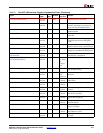
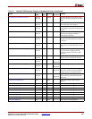
TRCC405TRACEDISABLE V-II Pro
and V-4
I Trace 0 Disables trace collection and
broadcast.
TRCC405TRIGGEREVENTIN V-II Pro
and V-4
ITrace0
Wrap to
Trigger
Event
Out
Indicates a trigger event occurred and
that trace status is to be generated.
a. V-II Pro = Virtex-II Pro; V-4 = Virtex-4
b. The ISE design tools assign drivers automatically.
Table B-1: PowerPC 405 Interface Signals in Alphabetical Order (Continued)
Signal
FPGA
Type
a
I/O
Type
Interface
If Unused
Ties To:
b
Function


