


PowerPC™ 405 Processor Block Reference Guide www.xilinx.com 23
UG018 (v2.0) August 20, 2004 1-800-255-7778
R
Real Mode
In real mode, programs address physical memory directly.
Virtual Mode
In virtual mode, programs address virtual memory and virtual-memory addresses are
translated by the processor into physical-memory addresses. This allows programs to
access much larger address spaces than might be implemented in the system.
Addressing Modes
Whether the PowerPC 405 is running in real mode or virtual mode, data addressing is
supported by the load and store instructions using one of the following addressing modes:
x Register-indirect with immediate index — A base address is stored in a register, and a
displacement from the base address is specified as an immediate value in the
instruction.
x Register-indirect with index — A base address is stored in a register, and a
displacement from the base address is stored in a second register.
x Register indirect — The data address is stored in a register.
Instructions that use the two indexed forms of addressing also allow for automatic updates
to the base-address register. With these instruction forms, the new data address is
calculated, used in the load or store data access, and stored in the base-address register.
With sequential instruction execution, the next-instruction address is calculated by adding
four bytes to the current-instruction address. In the case of branch instructions, the next-
instruction address is determined using one of four branch-addressing modes:
x Branch to relative — The next-instruction address is at a location relative to the
current-instruction address.
x Branch to absolute — The next-instruction address is at an absolute location in
memory.
x Branch to link register — The next-instruction address is stored in the link register.
x Branch to count register — The next-instruction address is stored in the count register.
Data Types
PowerPC 405 instructions support byte, halfword, and word operands. Multiple-word
operands are supported by the load/store multiple instructions and byte strings are
supported by the load/store string instructions. Integer data are either signed or unsigned,
and signed data is represented using two’s-complement format.
The address of a multi-byte operand is determined using the lowest memory address
occupied by that operand. For example, if the four bytes in a word operand occupy
addresses 4, 5, 6, and 7, the word address is 4. The PowerPC 405 supports both big-endian
(an operand’s most significant byte is at the lowest memory address) and little-endian (an
operand’s least significant byte is at the lowest memory address) addressing.
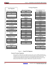
Register Set Summary
Figure 1-1 shows the registers contained in the PowerPC 405. Descriptions of the registers
are in the following sections.