


46 www.xilinx.com PowerPC™ 405 Processor Block Reference Guide
1-800-255-7778 UG018 (v2.0) August 20, 2004
Chapter 2: Input/Output Interfaces
R
RSTC405RESETSYS input to the processor block. When deasserted, no system-reset
request exists. Unlike GSR, this output has no associated reset connectivity in the FPGA.
The processor asserts this signal when one of the following occurs:
x A JTAG debugger sets the reset field in the debug-control register 0 (DBCR0[RST]) to
0b11.
x Software sets the reset field in the debug-control register 0 (DBCR0[RST]) to 0b11.
x The timer-control register watchdog-reset control field (TCR[WRC]) is set to 0b11 and
a watchdog time-out causes the watchdog-event state machine to enter the reset state.
RSTC405RESETCORE (Input)
External logic asserts this signal to reset the processor block (core). This includes the
PowerPC 405 core logic, data cache, instruction cache, and the interface controllers. The
PowerPC 405 also uses this signal to record a core reset type in the DBSR[MRR] field. This
signal should be asserted for at least eight clock cycles to guarantee that the processor
block initiates its reset sequence. No reset occurs and none is recorded in DBSR[MRR]
when this signal is deasserted.
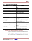
Table 2-5, page 44 shows the valid combinations of the RSTC405RESETCORE,
RSTC405RESETCHIP, and RSTC405RESETSYS signals and their effect on the DBSR[MRR]
field following reset.
RSTC405RESETCHIP (Input)
External logic asserts this signal to reset the chip. A chip reset involves the FPGA logic, on-
chip peripherals, and the processor block (the PowerPC 405 core logic, data cache,
instruction cache, and the interface controllers). The signal does not reset logic in the
processor block. The PowerPC 405 uses this signal only to record a chip reset type in the
DBSR[MRR] field. The RSTC405RESETCORE signal must be asserted with this signal to
cause a core reset. Both signals must be asserted for at least eight clock cycles to guarantee
that the processor block recognizes the reset type and initiates the core-reset sequence. The
PowerPC 405 does not record a chip reset type in DBSR[MRR] when this signal is
deasserted.
Table 2-5, page 44 shows the valid combinations of the RSTC405RESETCORE,
RSTC405RESETCHIP, and RSTC405RESETSYS signals and their effect on the DBSR[MRR]
field following reset.
RSTC405RESETSYS (Input)
External logic asserts this signal to reset the system. A system reset involves logic external
to the FPGA, the FPGA logic, on-chip peripherals, and the processor block (the PowerPC
405 core logic, data cache, instruction cache, and the interface controllers). This signal
resets the logic in the PowerPC 405 JTAG unit, but it does not reset any other processor
block logic. The PowerPC 405 uses this signal to record a system reset type in the
DBSR[MRR] field. The RSTC405RESETCORE signal must be asserted with this signal to
cause a core reset. The RSTC405RESETCORE, RSTC405RESETCHIP, and
RSTC405RESETSYS signals must be asserted for at least eight clock cycles to guarantee
that the processor block recognizes the reset type and initiates the core-reset sequence. The
PowerPC 405 does not record a system reset type in DBSR[MRR] when this signal is
deasserted.
This signal must be asserted during a power-on reset to initialize the JTAG unit properly.