


158 www.xilinx.com PowerPC™ 405 Processor Block Reference Guide
1-800-255-7778 UG018 (v2.0) August 20, 2004
Chapter 3: PowerPC 405 OCM Controller
R
Note: See Table 3-8 for descriptions of the signals shown in Table 3-10, above.
Programmer’s Model
DCR Registers
Application software has read and write access to the DCR control registers within the
OCM controllers. Typically, mtdcr and mfdcr assembly language instructions are used to
write and read respectively from these registers.
Figure 3-11, page 162 and Figure 3-12, page 163 list the DCR control registers and the bit
definitions for the DSOCM interface for Virtex-II Pro and Virtex-4. Figure 3-13, page 164
and Figure 3-14, page 165 list the DCR control registers and the bit definitions for the
ISOCM interface for Virtex-II Pro and Virtex-4.
DSARC/ ISARC Registers
The ISOCM and DSOCM interfaces provide DCR registers (DSARC & ISARC) which
define the eight most significant (base) address bits of the ISOCM and DSOCM memory
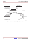
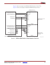
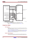
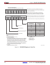
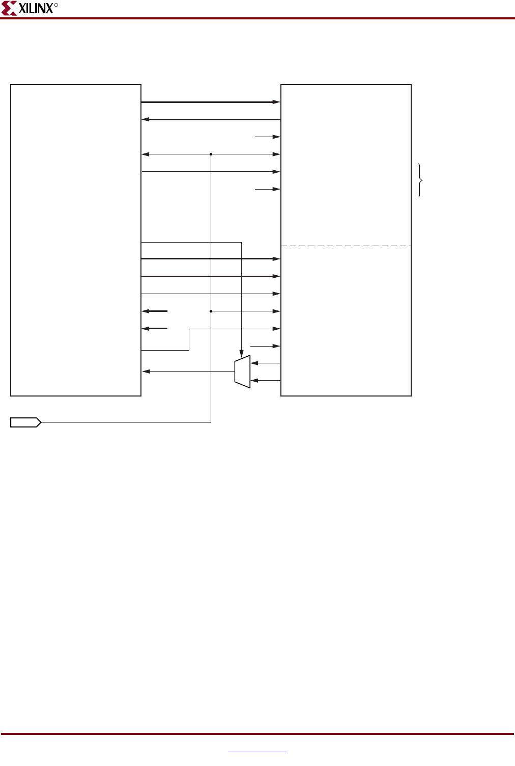
Figure 3-10: ISOCM to BRAM Interface: 8 KByte Example in Virtex-4
UG018_49b_04230
4
ISOCMBRAMRDABUS[19:28]
BRAMISOCMRDDBUS[0:63]
ISOCMBRAMEN
BRAMISOCMCLK
ISOCMBRAMWRDBUS[0:31]
ISOCMBRAMWRABUS[19:28]
ISOCMDCRBRAMRDSELECT
ISOCMBRAMODDWRITEEN
ISOCMBRAMEVENWRITEEN
ISOCMDCRBRAMODDEN
ISOCMDCRBRAMEVENEN
BRAMISOCMDCRRDBUS[0:31]
ISCNTLVALUE[0:7]
ISARCVALUE[0:7]
ADDRB[9:0]
DOB[15:0]
WEB
CLKB
ENB*
SSRB
(RAMB16S18S18) X 4
(2 for Odd words, 2 for Even)
ADDRA[13:4]
PORT B
PORT A
DIA[15:0]
WEA
CLKA
ENA*
SSRA
DOA(odd)
DOA(even)
(BRAMISOCMCLK from DCM)
*ENA can be tied off
permanently for higher
performance.
Global signals from FPG
A
system interface