PowerPC™ 405 Processor Block Reference Guide www.xilinx.com 79
UG018 (v2.0) August 20, 2004 1-800-255-7778
R
an aborted data-write request. In this case, memory must not be updated by the PLB slave
and no further write acknowledgements can be presented by the PLB slave for the aborted
request.
The DCU only aborts a data-access request when the processor is reset. Such an abort can
occur during an address-pipelined data-access request while the PLB slave is responding
to a previous data-access request. If the PLB is not also reset (as is the case during a core
reset), the PLB slave is responsible for completing the previous request and aborting the
new (pipelined) request.
C405PLBDCUWRDBUS[0:63] (Output)
This write-data bus contains the data transferred from the DCU to a PLB slave during a
write transfer. The operation of this bus depends on the transfer size, as follows:
x During a single word write, the write-data bus is valid when the write request is
presented by the DCU. The data remains valid until the PLB slave accepts the data.
The PLB slave asserts the write-data acknowledgement signal when it latches data
transferred on the write-data bus, indicating that it accepts the data. This completes
the word write.
The DCU replicates the data on the high and low words of the write data bus (bits
[0:31] and [32:63], respectively) during a single word write. The byte enables indicate
which bytes on the high word or low word are valid and should be latched by the PLB
slave.
x During an eight-word line transfer, the write-data bus is valid when the write request
is presented by the DCU. The data remains valid until the PLB slave accepts the data.
The PLB slave asserts the write-data acknowledgement signal when it latches data
transferred on the write-data bus, indicating that it accepts the data. In the cycle after
the PLB slave accepts the data, the DCU presents the next word or doubleword of
data (depending on the PLB slave size). Again, the PLB slave asserts the write-data
acknowledgement signal when it latches data transferred on the write-data bus,
indicating that it accepts the data. This continues until all eight words are transferred
to the PLB slave.
Data is transferred from the DCU to the PLB slave in ascending address order. Word 0
(lowest address of the cache line) is transferred first, and word 7 (highest address) is
transferred last. The byte enables are not used during a line transfer and must be
ignored by the PLB slave.
The location of data on the write-data bus depends on the size of the PLB slave, as
follows:
i If the slave has a 64-bit bus, the DCU transfers even words (words 0, 2, 4, and 6)
on write-data bus bits [0:31] and odd words (words 1, 3, 5, and 7) on write-data
bus bits [32:63]. Four doubleword writes are required to complete the eight-word
line transfer. The first transfer writes words 0 and 1, the second transfer writes
words 2 and 3, and so on.
i If the slave has a 32-bit bus, the DCU transfers all words on write-data bus bits
[0:31]. Eight doubleword writes are required to complete the eight-word line
transfer. The first transfer writes word 0, the second transfer writes word 1, and so
on.
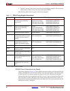
Table 2-15 summarizes the location of words on the write-data bus during an eight-
word line transfer.


