


PowerPC™ 405 Processor Block Reference Guide www.xilinx.com 133
UG018 (v2.0) August 20, 2004 1-800-255-7778
R
FPGA logic can combine these signals with the trigger-event output signal to produce a
qualified version of the trigger signal. The qualified signal is wrapped to the trigger-event
input signal in the same trace cycle. The external trace tool also monitors the trigger-event
input signal to synchronize its own trace collection. This capability can be used to
implement various trace collection schemes.
C405TRCCYCLE (Output)
This signal defines the cycle that execution status and trace status are broadcast on the
trace interface (this is referred to as the trace cycle). Although the PowerPC 405 collects
execution status and trace status every processor cycle, the information is made available
to the trace interface once every two cycles. The information collected during those two
cycles is broadcast over the trace interface in a single trace cycle. For this reason, the trace
cycle is produced by the processor once every two processor clocks. Operating the trace
interface in this manner helps reduce the amount of I/O switching during trace collection.
C405TRCEVENEXECUTIONSTATUS[0:1] (Output)
These signals are used to specify the execution status collected during the first of two
processor cycles. The PowerPC 405 collects execution status and trace status every
processor cycle, but the information is made available to the trace interface once every two
cycles. The information collected during those two cycles is broadcast over the trace
interface in a single trace cycle.
C405TRCODDEXECUTIONSTATUS[0:1] (Output)
These signals are used to specify the execution status collected during the second of two
processor cycles. The PowerPC 405 collects execution status and trace status every
processor cycle, but the information is made available to the trace interface once every two
cycles. The information collected during those two cycles is broadcast over the trace
interface in a single trace cycle.
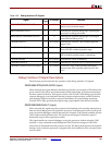
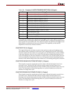
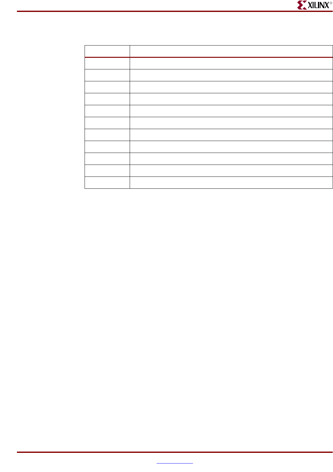
Table 2-28: Purpose of C405TRCTRIGGEREVENTTYPE[0:10] Signals
Bit Debug Event
0 Instruction Address Compare 1 (IAC1)
1 Instruction Address Compare 2 (IAC2)
2 Instruction Address Compare 3 (IAC3)
3 Instruction Address Compare 4 (IAC4)
4 Data Address Compare 1 (DAC1)—Read
5 Data Address Compare 1 (DAC1)—Write
6 Data Address Compare 2 (DAC2)—Read
7 Data Address Compare 2 (DAC2)—Write
8 Trap Instruction (TDE)
9Exception Taken (EDE)
10 Unconditional (UDE)