


56 www.xilinx.com PowerPC™ 405 Processor Block Reference Guide
1-800-255-7778 UG018 (v2.0) August 20, 2004
Chapter 2: Input/Output Interfaces
R
x When a 64-bit PLB slave responds, an aligned doubleword is sent from the slave to the
ICU during each transfer cycle. Both words are read from the 64-bit interface by the
ICU in this cycle.
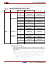
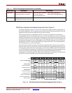
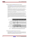
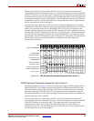
Table 2-10, page 58, shows the location of instructions on the ICU read-data bus as a
function of PLB-slave size, line-transfer size, and transfer order.
PLBC405ICURDDACK (Input)
When asserted, this signal indicates the ICU read-data bus contains valid instructions sent
by the PLB slave to the ICU (read data is acknowledged). The ICU latches the data from the
bus at the end of the cycle this signal is asserted. The contents of the ICU read-data bus are
not valid when this signal is deasserted.
Read-data acknowledgement is asserted for one cycle per transfer. There is no limit to the
number of cycles between two transfers. The number of transfers (and the number of read-
data acknowledgements) depends on the following:
x The PLB slave size (bus width) specified by PLBC405ICUSSIZE1.
x The line-transfer size specified by C405PLBICUSIZE[2:3].
x The cacheability of the fetched instructions specified by C405PLBICUCACHEABLE.
x The value of the non-cacheable request-size bit (CCR0[NCRS]).
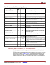
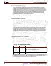
Table 2-9 summarizes the effect these parameters have on the number of transfers.
PLBC405ICURDDBUS[0:63] (Input)
This read-data bus contains the instructions transferred from a PLB slave to the ICU. The
contents of the bus are valid when the read-data acknowledgement signal
(PLBC405ICURDDACK) is asserted. This acknowledgment is asserted for one cycle per
transfer. There is no limit to the number of cycles between two transfers. The bus contents
are not valid when the read-data acknowledgement signal is deasserted.
The PLB slave returns either a single instruction (an aligned word) or two instructions (an
aligned doubleword) per transfer. The number of instructions sent per transfer depends on
the PLB slave size (bus width), as follows:
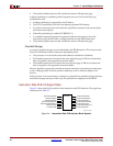
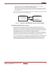
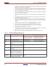
x When a 32-bit PLB slave responds, an aligned word is sent from the slave to the ICU
during each transfer cycle. The 32-bit PLB slave bus should be connected to both the
high and low 32 bits of the 64-bit read-data bus, as shown in Figure 2-5 below. This
type of connection duplicates the word returned by the slave across the 64-bit bus.
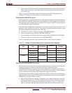
Table 2-9: Number of Transfers Required for Instruction-Fetch Requests
PLB-Slave
Size
Line-Transfer
Size
Instruction
Cacheability
CCR0[NCRS]
Number of
Transfers
32-Bit Four Words Non-Cacheable 0 4
Eight Words 1 8
Eight Words Cacheable — 8
64-Bit Four Words Non-Cacheable 0 2
Eight Words 1 4
Eight Words Cacheable — 4