104 www.xilinx.com PowerPC™ 405 Processor Block Reference Guide
1-800-255-7778 UG018 (v2.0) August 20, 2004
Chapter 2: Input/Output Interfaces
R
Virtex-4-FX
The external general purpose DCR interface in Virtex-4-FX is identical to its predecessors
with the following exceptions:
x Dedicated, re-synchronization registers implemented in the PowerPC block.
x Interface signals have been renamed
The re-synchronization registers allow decoupling of the internal PowerPC clock
frequency from the DCR bus transactions by re-synchronizing the interface to a dedicated
DCR clock (CPMDCRCLK, see “Clock and Power Management Interface”). This ensures
that the internal PowerPC clock frequency can be kept high regardless of DCR transaction
speed.
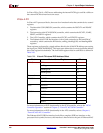
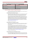
The table below describes the name mapping between the DCR interface signals in
Virtex-4-FX relative to Virtex-II Pro and Virtex-II ProX.
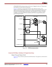
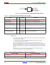
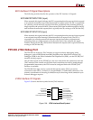
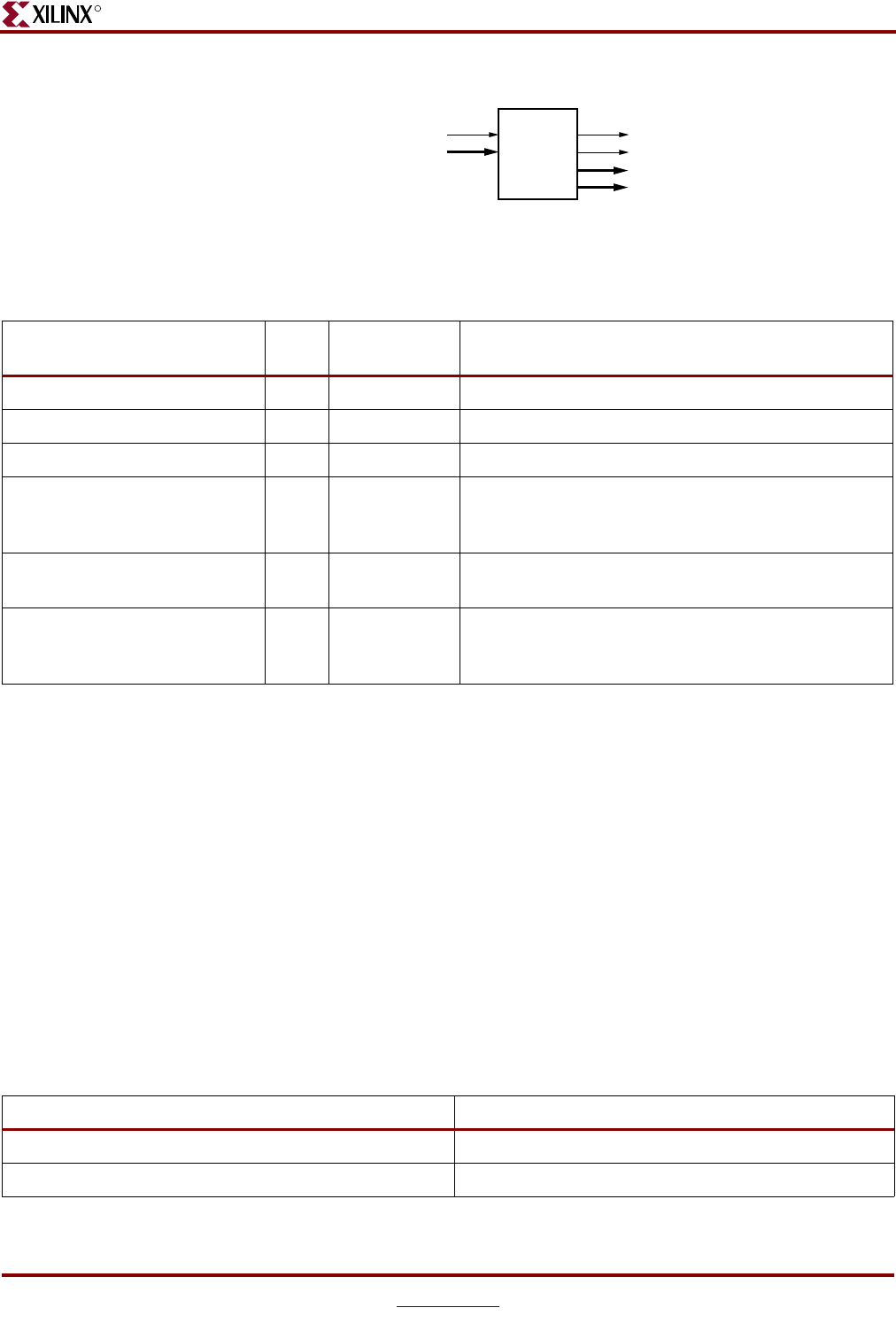
Figure 2-32: Virtex-II Pro and Virtex-II ProX DCR Interface Block Symbol
UG018_06_020702
PPC405
DCRC405ACK
DCRC405DBUSIN[0:31]
C405DCRREAD
C405DCRWRITE
C405DCRABUS[0:9]
C405DCRDBUSOUT[0:31]
Table 2-21: Virtex-II Pro and Virtex-II ProX DCR Interface I/O Signals
Signal
I/O
Type
If Unused Function
C405DCRREAD O No Connect Indicates a DCR read request occurred.
C405DCRWRITE O No Connect Indicates a DCR write request occurred.
C405DCRABUS[0:9] O No Connect Specifies the address of the DCR access request.
C405DCRDBUSOUT[0:31] O No Connect
or attach to
input bus
The 32-bit DCR write-data bus.
DCRC405ACK I 0 Indicates a DCR access has been completed by a
peripheral.
DCRC405DBUSIN[0:31] I 0x0000_0000
or attach to
output bus
The 32-bit DCR read-data bus.
Table 2-22: Virtex-4-FX DCR Interface Name Correlation with Virtex-II Pro/ProX
Virtex-4-FX Name Virtex-II Pro/ProX Name
EXTDCRREAD C405DCRREAD
EXTDCRWRITE C405DCRWRITE


