


Reelmaster 5010- H Hydraulic SystemPage 4 - 63
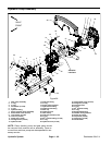
Removal (Fig. 56)
1. Park themachine on alevel surface,engage parking
brake, lower cutting units and stop engine. Remove key
from the ignition switch.
2. Raise and support hood and operator seat. Lift hood
saddle from frame brackets and remove from machine.
3. Read the General Precautions for Removing and
Installing Hydraulic System Components at the begin-
ning of the Service and Repairs section of this chapter.
CAUTION
Before opening hydraulic system, operate all hy-
draulic controls to relieve system pressure and
avoid injury from pressurized hydraulic oil. See
Relieving HydraulicSystem Pressurein the Gen-
eral Information section of this chapter.
4. To prevent contamination of the hydraulic system,
thoroughly clean piston (traction) and gear pump as-
sembly and all hydraulic connections.
5. Label hydraulic hoses to assist in assembly. Discon-
nect all hydraulic hoses and tubes from fittings on the
piston (traction) and gear pump assembly. Allow hy-
draulic lines to drain into a suitable container. Plug or
cap openings of pumps and lines to prevent contamina-
tion.
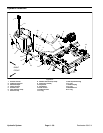
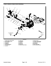
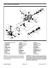
6. Remove two(2) capscrews(item36)andflangenuts
(item 37) that secure pump drive shaft to piston (trac-
tion) pump input shaft.
7. Disconnect traction control cable from piston (trac-
tion) pump (see Piston (Traction) Pump Control Assem-
bly in this section). Carefully position traction control
cable away from piston pump.
8. Disconnect wire harness electrical connector from
traction neutral switch on piston pump control assembly
and position harness away from pump assembly.
IMPORTANT: Dry weight of pump assembly is ap-
proximately 68 pounds (31 kg).
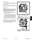
9. Connect a lift or hoist tohole in traction cable bracket
onpiston pumpto supportpump assemblyand forpump
removal.
10.Loosen and remove two (2) carriage screws (item
12) and flange nuts (item 11) that secure pump support
bracket to frame.
11.Remove two (2) flange screws (item 27) and flange
nuts (item 28) that secure piston (traction) pump flange
to machine frame.
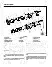
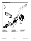
1. Piston (traction) pump
2. Gear pump
3. Traction cable bracket
Figure 57
2
1
3
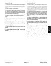
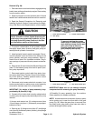
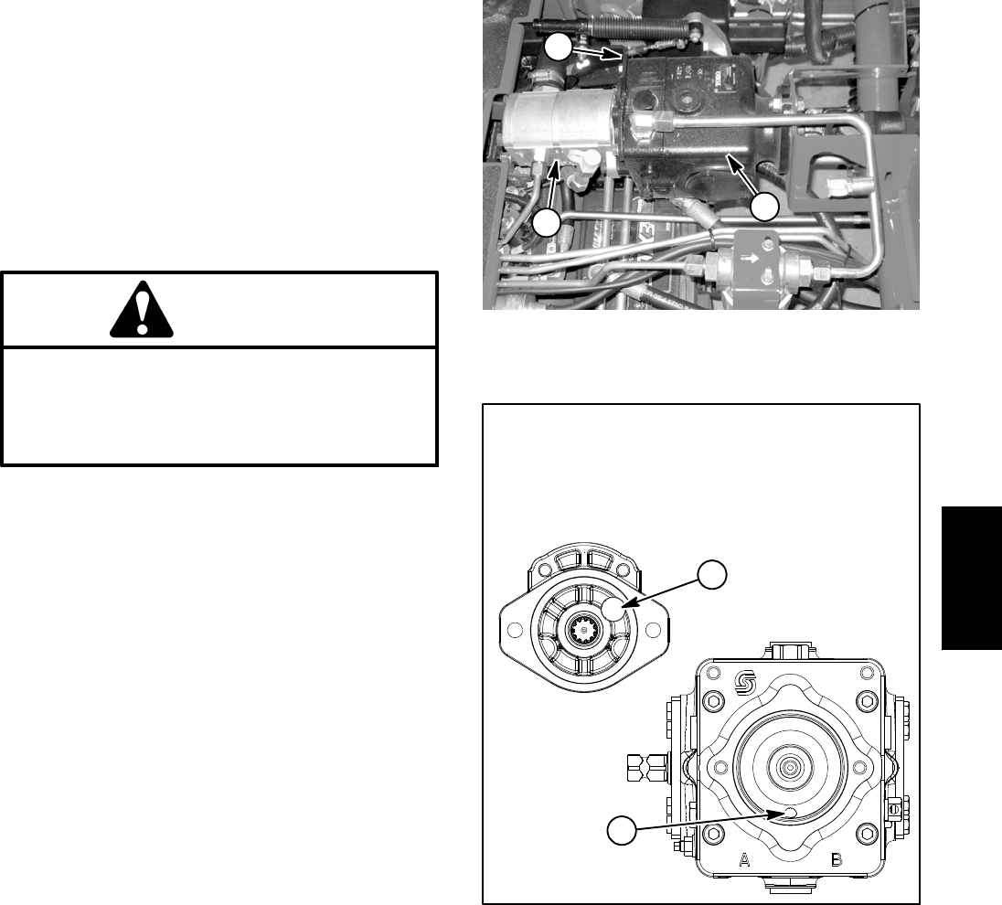
1. Piston pump case drain 2. Gear pump suction port
Figure 58
after gear pump is removed.
drain and gear pump suction port
install plugs in piston pump case
To prevent draining the pumps,
Remove plugs before installing
gear pump to piston pump.
2
1
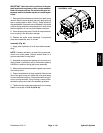
IMPORTANT: Make sure to not damage machine
components while removing the pump assembly.
12.Carefully lift pump assembly from the machine.
Place assembly on suitable workbench.
NOTE: A case drain exists inthe piston (traction) pump
and a suction port is near the input shaft of the gear
pump (Fig. 58). When the g ear pump is removed from
the piston pump, plug piston pump case drain hole to
prevent draining the piston pump.
Hydraulic
System