


Reelmaster 5010- H
Cutting Units
Page 7 - 27
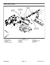
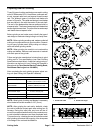
Assembly of Cutting Reel (Fig. 31)
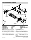
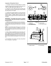
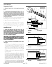
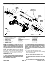
1. If removed, install new reel shaft plugs into cutting
reel shaft. Plugs should be recessed into reel shaft from
1.370” to 1.630” (34.8 to 41.4 mm) (Fig. 33).
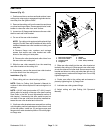
2. Install two (2) new retaining rings onto cutting reel
shaft. Make sure that the retaining rings are fully seated
into the grooves on the shaft.
3. Carefully drive special washers onto reel shaft with
beveled side of washers toward reel ( flat side toward
bearing location). Installed washers should be tight
against retaining ring and should not wobble as the reel
is rotated.
IMPORTANT: The flocked seal should be installed
so the flocked (red) side of the seal is toward the
bearing location.
4. Slide flocked seals (flocked (red) side orientated to-
ward bearinglocation) andbearingsf ully ontoreelshaft.
Flocked seals and bearings should bottom on reel shaft
shoulder.
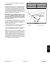
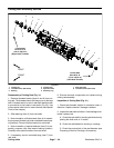
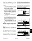
NOTE: The threaded insert with the groove on the face
has LH threads and should be installed in end of reel
shaftidentified withagroove thatis justinsideofreelspi-
der (Fig. 32).
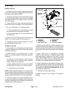
5. Clean threads of threaded inserts and cutting reel
shaft. Apply Loctite#242 (or equivalent) tothreads of in-
serts, thread inserts into reel shaft and torque from 85
to 95 ft-lb (115 to 128 N- m). Use correct spline insert
tool forinsert installation(see Special Toolsin this chap-
ter).
6. Fill threaded insert splines with high temp Mobil
XHP- 222 grease or equivalent.
1. Cutting reel
2. Reel shaft groove
3. Insert with LH threads
4. Groove on face
5. Insert with RH threads
Figure 32
2
1
5
3
4
1. Cutting reel shaft 2. Reel shaft plug
Figure 33
1.370” to 1.630”
(34.8 to 41.4 mm)
2
1
Cutting
Units