


Reelmaster 5010- HPage 5 - 50Electrical System
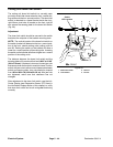
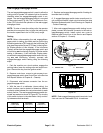
Reel Engage/Disengage Switch
The reel engage/disengage switch is used to allow the
cutting units to operate. An indicator light on the switch
identifies when the engage/disengage switch is en-
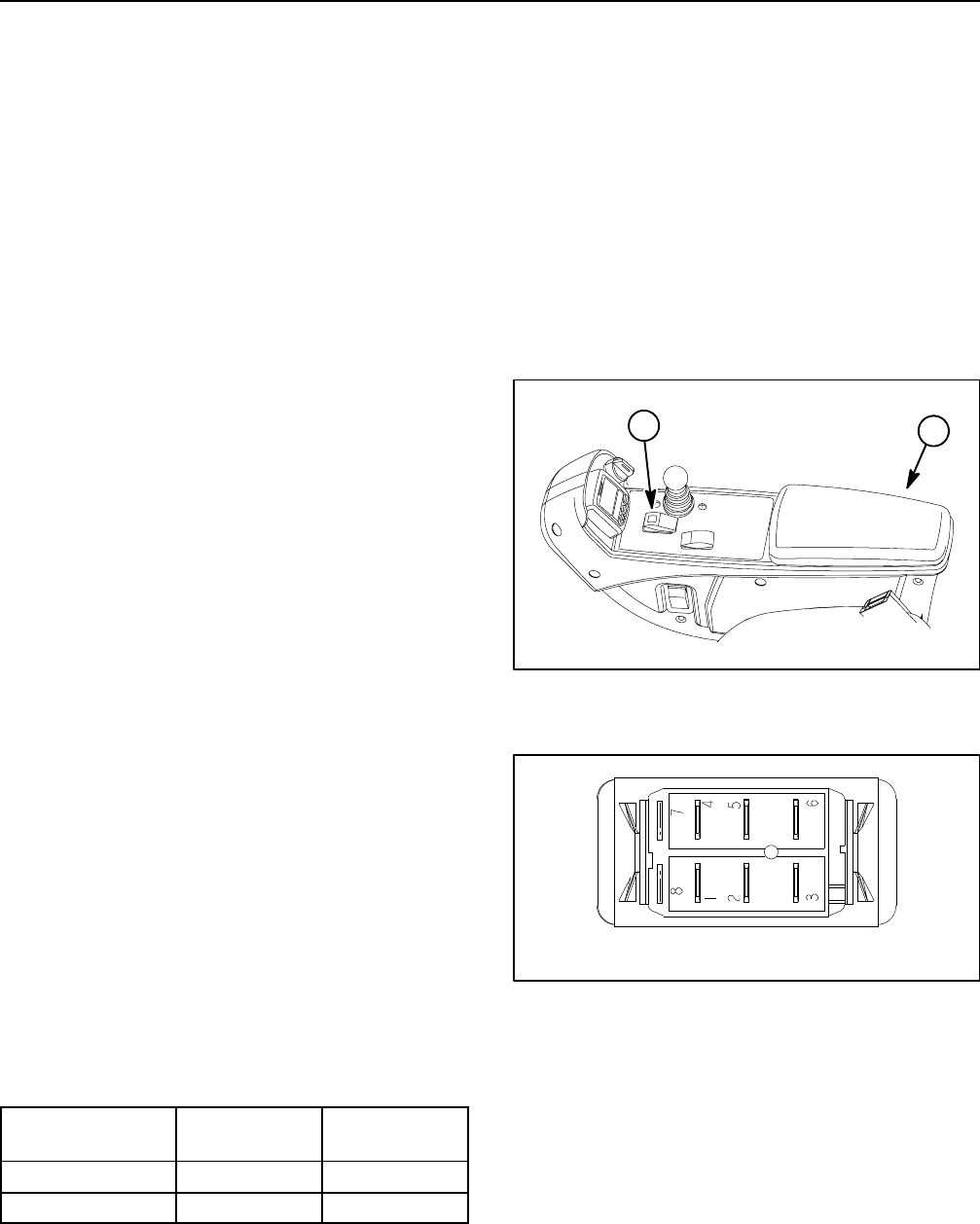
gaged. The reel engage/disengage switch is mounted
on the control panel (Fig. 39). The Toro Electronic Con-
troller (TEC) monitors the operation of the reel engage/
disengage switch.
NOTE: To raise or lower the cutting units, the operator
seat has to be occupied. Also, to lower the cutting units,
thetractionspeedhastobeinLOW(mow)range.
Testing
NOTE: Before disconnecting the reel engage/disen-
gage switch for testing, the switch and its circuit wiring
should betested as aTEC input withthe InfoCenter Dis-
play(seeDiagnostics Screen(PTOitem) inthe InfoCen-
ter Display section of this chapter). If the InfoCenter
Display verifies that the engage/disengage switch and
circuit wiring are functioning correctly, no further switch
testing is necessary. If the InfoCenter Display deter-
mines that the engage/disengage switch and circuit wir-
ing are not functioning correctly, proceed with
engage/disengage switch testing using the following
steps.
1. Park the machine on a level surface, engage the
parking brake, lower the cutting units and stop the en-
gine. Remove the key from the ignition switch.
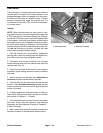
2. Remove control arm covers to gain access to en-
gage/disengage switch (see Control Arm in the Service
and Repairs section of Chapter 6 - Chassis).
3. Disconnect wire harness connector from the en-
gage/disengage switch.
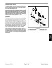
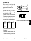
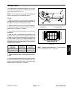
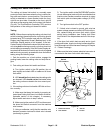
4. With the use of a multimeter (ohms setting), the
switch functions can be tested to determine whether
continuity exists between the various terminals for each
switch position. The reel engage/disengage switch ter-
minals are marked as shown in Figure 40. The circuitry
of this switch is shown in the chart below. Verifycontinu-
ity between switch terminals.
SWITCH
POSITION
NORMAL
CIRCUITS
OTHER
CIRCUITS
ON 2+3 5+6
OFF 2+1 5+4
5. Replace reel engage/disengage switch if testing de-
termines that it is faulty.
6. If engage/disengage switch tests correctly and cir-
cuit problem still exists, check circuit wire harness (see
Electrical Schematic and Circuit Drawings in Chapter 9
- Foldout Drawings).
7. After reel engage/disengage switch testing is com-
pleted, connect wire harness connector to the reel en-
gage/disengage switch. Install control arm cover to
machine (see Control Arm in the Service and Repairs
section of Chapter 6 - Chassis).
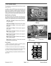
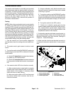
Figure 39
1
2
1. Console arm 2. Reel switch
Figure 40
BACK OF SWITCH
NOTE: Reel engage/disengage switch terminals 1 and
4 are not used on Reelmaster 5010- H machines.