


Reelmaster 5010- H
Cutting Units
Page 7 - 22
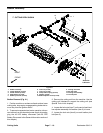
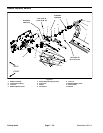
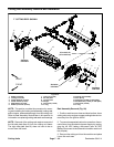
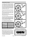
Cutting Reel Assembly Removal and Installation
1. Bedbar assembly
2. Cutting unit frame
3. Flange bushing (2 used)
4. Plastic washer (4 used)
5. Metal washer (2 used)
6. Bedbar pivot bolt (2 used)
7. Lock nut (2 used)
8. RH side plate
9. LH side plate
10. Weight
11. Cap screw (2 used)
12. O-ring
13. Cutting reel assembly
14. Wire s pring
15. Flange nut (3 used per side plate)
16. Shoulder bolt (3 used per side plate)
17. Cap screw ( 2 used)
18. O-ring
Figure 28
Antiseize
Lubricant
FRONT
RIGHT
7” CUTTING REEL SHOWN
2
3
6
8
9
10
11
13
1
5
7
12
14
15
16
17
18
4
4
27 to 33 ft-lb
(37to44N-m)
Antiseize
Lubricant
Antiseize
Lubricant
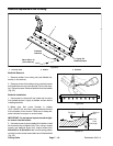
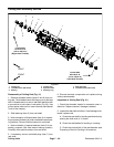
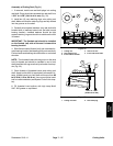
NOTE: This section provides the procedure for remov-
ing and installing the cutting reel assembly (cutting reel,
spline inserts, seals and bearings) from the cutting unit.
Refer to Reel Assembly Service later in this section for
informationon replacingcutting reelseals andbearings.
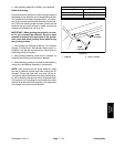
NOTE: Removal of the cutting reel requires removal of
the left side plate (item 9) f rom the cutting unit frame.
The right side plate (item 8) does not have to be re-
moved from the frame.
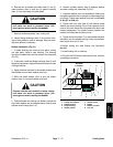
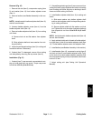
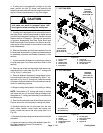
Reel Assembly Removal (Fig. 28)
1. Position machine on aclean and level surface,lower
cutting units, stopengine, engageparking brake andre-
move key from the ignition switch.
2. To preventunexpected reel motor operation,discon-
nect motors from the electrical power supply by unplug-
ging the 48 VDC battery disconnect (see 48 VDC
BatteryDisconnectin theGeneralInformation sectionof
this chapter).
3. Remove the cutting unit from the machine and place
it on a flat work area.