


Reelmaster 5010- HPage 5 - 88Electrical System
Cutting Reel Motor
NOTE: If electrical problems exist with a cutting reel
motor,afaultmay haveoccurredthatwould beindicated
bya faultcodeon theInfoCenterDisplay.Before consid-
ering that reel motor service work is necessary, check
for any existing fault codes that indicate problems with
a reel motor (see Fault Codes in the Troubleshooting
section of this chapter).
IMPORTANT: When performing service or mainte-
nance on the cutting reel motors, take care to not
damage the motors or electrical connections.
Removal
1. Park machine on level surface, lower cutting units,
stop engine, apply parking brake and remove key from
ignition switch.
2. Separate system components from the 48 VDC bat-
tery pack by unplugging the 48 VDC battery disconnect.
(see48VDC BatteryDisconnectinthe GeneralInforma-
tion section of this chapter). This will prevent unex-
pected 48 VDC system component operation.
IMPORTANT: When removing cutting reel motor,
take care to not damage the cable. The cable is not
available as a replacement part.
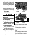
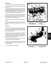
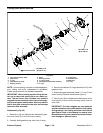
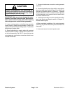
3. Remove cuttingreel motorfrom cuttingunit (Fig.91):
A. Loosen two(2) capscrewsthatsecure thecutting
reel motor t o the cutting unit side plate.
B. Rotate motor clockwise to disengage motor
flange from cap screws and remove motor from cut-
ting unit. Position and support reel motor away from
cutting unit.
4. Remove O- ring from flange of motor and discard
O-ring.
5. Inspect cutting reel threaded insert splines for wear.
Replace inserts if necessary (see Cutting Reel Assem-
bly in the Service and Repairs section of Chapter 7 Cut-
ting Units).
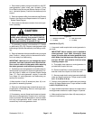
6. The cutting unit side plates have threaded inserts at
the locations used for the cap screws that secure the
reel motor. Check the condition of the threaded inserts
andreplaceinserts ifdamageis found.Insertsshouldbe
torquedfrom 35to 40ft- lb(48to 54N-m) during instal-
lation.
7. Place protective plasticcap (see Special Tools inthis
chapter) into the hole in the cutting unitside plate to pre-
vent debris entry into reel bearing area.
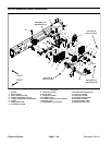
1. Cutting reel motor 2. Cap screw
Figure 91
1
2
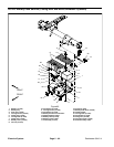
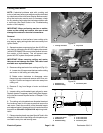
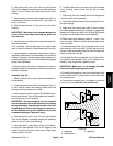
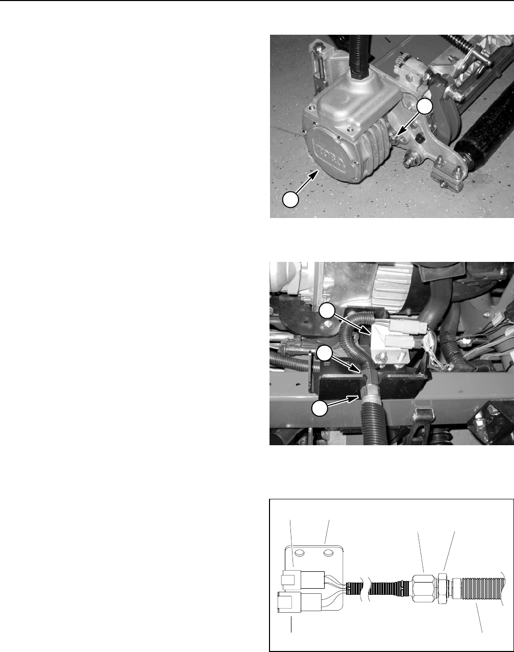
1. Bulkhead nut
2. Bulkhead fitting
3. Connector plate
Figure 92
1
2
3
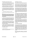
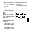
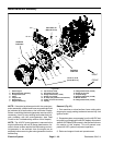
1. Cable from motor
2. Bulkhead nut
3. Bulkhead fitting
4. 4 wire connector
5. 2 wire connector
6. Connector plate
Figure 93
23
15
4
6