


Reelmaster 5010- H
Cutting Units
Page 7 - 37
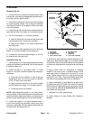
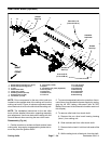
Assembly (Fig. 48)
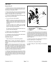
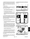
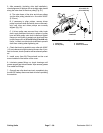
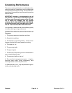
1. Install drive shaft if it was removed (Fig. 49):
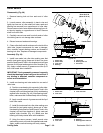
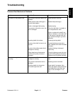
IMPORTANT: If rear roller brush drive is on left
side of cutting unit, drive shaft has left hand
threads and can be identified by a groove on the
flange. If the rear roller brush drive is on right
side of cutting unit, drive shaft has right hand
threadsanddoesnot haveagrooveon theflange
(Fig. 50).
A. Apply Loctite #242 (or equivalent) to threads of
drive shaft. Thread drive shaft into cutting reel and
torque from 85 to 95 ft- lb (115 to 128 N-m).
B. Makesure thatO- ringis placedoninner flangeof
drive housing.
C. Position housing to cutting unit side plate and se-
cure to cutting unit with two (2) socket head screws.
D. Make surethat grommet groove is correctly seat-
ed on flange in drive housing bore.
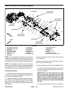
2. Assemble roller brush components using Figure 48
as a guide.
A. During assembly, apply Loctite #242 (or equiva-
lent) to threads of fasteners and torque fasteners as
shown in Figure 48.
B. Apply a light coating of grease to inner diameter
of the grommet in drive bearing housing before in-
stalling brush plate.
C. Brushplateshouldbeinstalledsothatidlerpulley
assembly is toward the bottom of the plate. Also, the
shoulder bolt (item 15) should not clamp the brush
plate to the drive housing during assembly.
D. When installing drive pulley (item 17), make sure
that tabs on pulley engage slot in drive shaft.
E. Idlerarm (item7) shouldbe freeto rotateafter as-
sembly to brush plate. Make sure that idler spring is
installed so that it can rotate the idler arm and pulley
and apply tension to the drive belt.
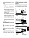
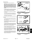
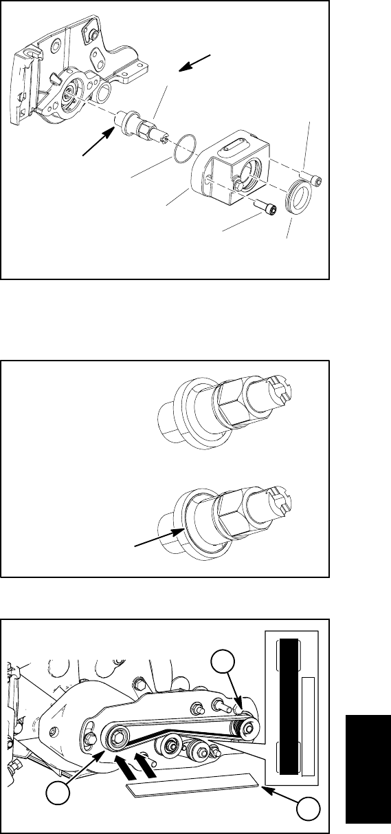
F. After drive belt installation, make sure that the
ribs on the belt are properly seated in the grooves of
boththedriveand drivenpulleysandthatthe beltisin
the center of the idler pulley.
1. Drive housing
2. Drive shaft
3. O-ring
4. Socket head screw
5. Grommet
Figure 49
1
2
3
4
5
4
NOTE: 5” CUTTING UNIT SHOWN
85 to 95 ft-lb
(115 to 128 N-m)
Loctite #242
Figure 50
Drive Shaft
With RH Threads
(No Groove)
Drive Shaft
With LH Threads
(With Groove)
1. Driven pulley
2. Drive pulley
3. Straight edge
Figure 51
2
1
3
Cutting
Units