


Reelmaster 5010- H Page 5 - 69 Electrical System
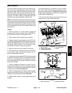
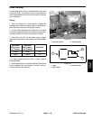
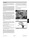
CAN- bus Termination Resistors
System communication between electrical components
on Reelmaster 5010- H machines is accomplished on
two (2) CAN- bus communication systems: one fo r the
12 VDC systemand one for the48 VDC system. Two (2)
specially designed, twisted cables form the bus for both
of the networks used on the 5010- H machines. These
wiresprovidethe datapathwaysbetween machineelec-
trical components. At the ends of the twisted pair of bus
cables are 120 oh m termination resistors.
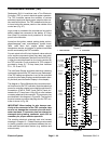
The twisted pair of bus wires for the 12 VDC circuits are
black/white a nd red/white. The twisted pair of bus wires
for t he 48 VDC circuits are green and yellow.
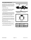
The two (2) termination resistors for the 12 VDC electri-
cal circuits have the following locations:
A. In the control arm next to the operator seat.
B. Near thewire harness connectors forthe #3(right
rear) cutting unit motor on the right side of the ma-
chine.
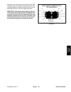
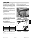
The two (2) termination resistors for the 48 VDC electri-
cal circuits have the following locations:
A. Nearthewireharnessconnectors forthe#1 (front
center) cutting unit motor under the footrest at the
front of the machine.
B. Near the 48 VDC reel motor fuse holder behind
the hood saddle under the hood.
NOTE: Refer to the Electrical Schematics and Wire
Harness Drawings in Chapter 9 - Foldout Drawings for
additional information on termination resistor locations
and wire connections.
IMPORTANT: The termination resistors at the ends
of the bus cables are required for proper electrical
system operation.
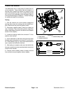
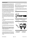
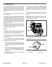
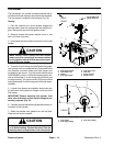
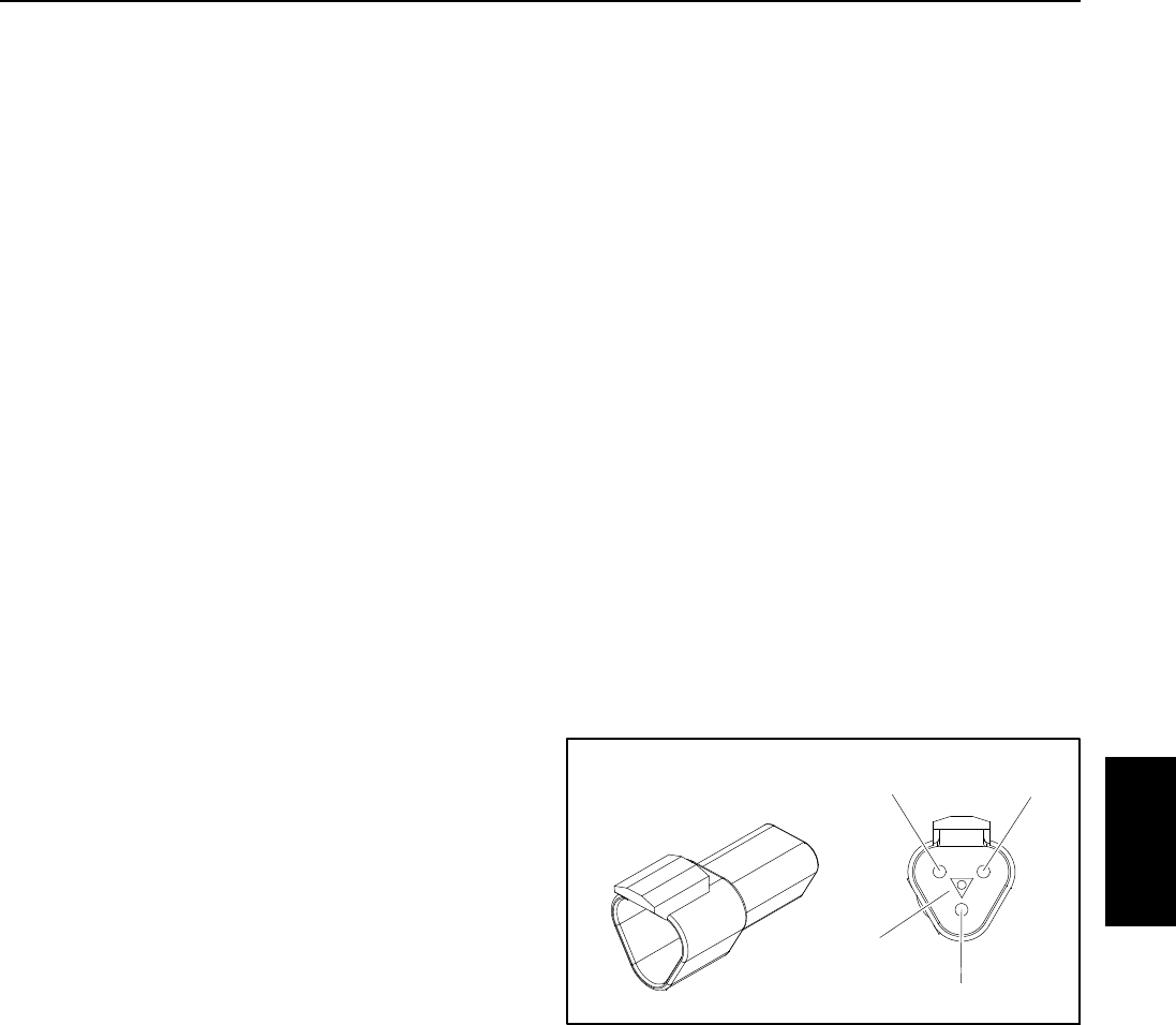
Termination Resistor Test
The termination resistors (Fig. 70) can be individually
tested using a digital multimeter (ohms setting). Locate
resistor and remove cable tie that secures resistor to
wire harness. Unplug the resistor from the wire harness
for testing.
NOTE: The insulator wedge in the termination resistor
is blue for identification purposes. There also is a center
keywaytopreventthe terminationresistor fromplugging
into the wrong wire harness connector.
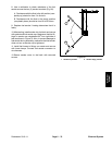
Use a digital multimeter (ohms setting) to measure the
resistance value for the termination resistor. There
should be 120 o hms resistance between terminals A
and B. Refer to Fig. 70 to determine terminal locations.
Terminal C is not used on Reelmaster 5010- H ma-
chines.
If testing determines that termination resistor is faulty,
replace resistor.
After testing is complete, make sure that termination re-
sistor is fully installed into wire harness connector and
securedtowireharnesswithcabletie.
Figure 70
Termination
A
B
C
Resistor
Keyway
Electrical
System