


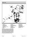

Reelmaster 5010- HPage 6 - 24Chassis
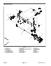
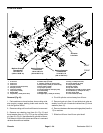
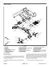
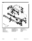
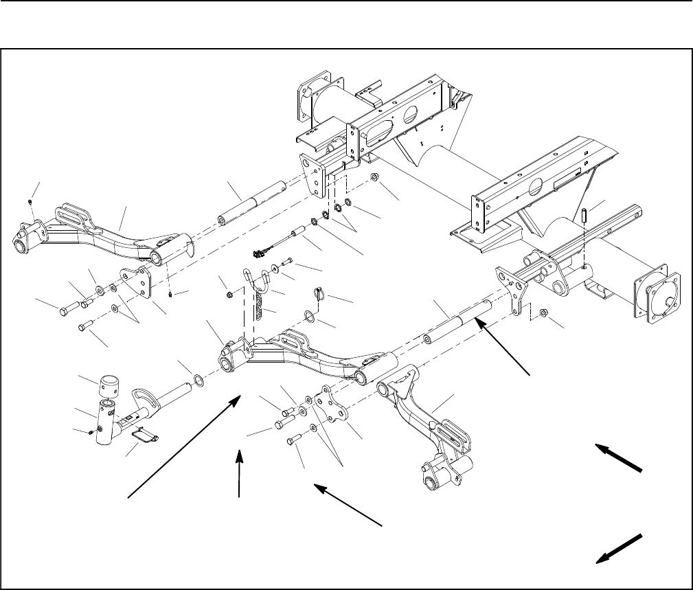
Front Lift Arms
1. #1 lift arm
2. #4 lift arm
3. #5 lift arm
4. Lift arm pivot shaft (3 used)
5. Roll pin (3 used)
6. Lock nut (4 used)
7. Cap screw (4 used)
8. Bridge plate
9. Cap screw (1 used per lift arm)
10. Chain hoop (3 used)
11. Washer (2 used per chain hoop)
12. Cap screw (2 used per chain hoop)
13. Pivot yoke ( 3 used)
14. Lynch pin (3 used)
15. Thrust washer (2 used per yoke)
16. Grease fitting
17. Bridge plate
18. Snapper pin (1 used per lift arm)
19. Cap (1 used per lift arm)
20. Thrust washer (6 used)
21. Cap screw ( 2 used)
22. Chain (3 used)
23. Up limit switch
24. Flange nut (2 used per chain hoop)
25. Flat washer (1 used per lift arm)
26. Jam nut (2 used)
27. Lock washer (2 used)
Figure 20
FRONT
RIGHT
75 to 95 ft-lb
(102 to 128 N-m)
135 to 165 ft-lb
(184 to 223 N-m)
2
3
6
8
9
10
11
13
1
5
7
12
14
15
16
17
18
19
20
4
21
22
23
24
25
26
27
16
21
25
9
7
20
15
4
6
16
26
Threadlocker
Medium Strength
Threadlocker
Medium Strength
75 to 95 ft- lb
(102 to 128 N-m)
Threadlocker
Medium Strength
Lubricant
Antiseize
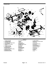
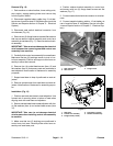
Removal (Fig. 20)
1. Park machine on a level surface, lower cutting units,
stop engine, engage parking brake and remove key
from the ignition switch.
2. Remove cuttingunitfromfrontlift armto beremoved.
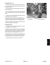
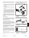
3. Remove one retaining ring (item 3 in Fig. 21) and
thrust washer (item 4 in Fig. 21) from the cylinder slide
pin (item 5 in Fig. 21) that secures lift cylinder to lift arm.
Pullslide pinfrom theliftcylinder andliftarm. Locateand
retrieve second thrust washer.
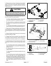
4. Pivot lift cylinder rod end away from lift arm.
5. Remove lynch pin (item 14) and slide pivot yoke as-
sembly from lift arm. Locate and retrieve two (2) thrust
washers (item 15).
6. Remove fastenersthat securebridge plate(item 8 or
17) to machine.
7. Slide front lift arm from lift arm pivot shaft.