


Reelmaster 5010- H Page 5 - 7 Electrical System
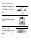
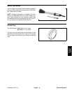
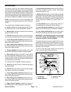
Cutting Reel Motor Rotor Tool Set
Toro Part Number: 127- 2574 (for both 5” and 7” cutting
unit motors)
The rotor tool set for the cutting reel motor is required to
remove and installthe rotorfrom thereel motorhousing.
Tool set includes puller hub, threaded shaft, handle and
four (4) screws (Fig. 6).
NOTE: Toro part number TOR6028 can be used to ser-
vice cutting unit motors on 5” cutting units and is also
used on other Toro products. TOR6028 will not work on
7” cutting unit motors.
NOTE: For cutting reel motor service procedures, see
Cutting Reel Motor Service in the Service and Repairs
section of this chapter.
IMPORTANT: When working on the cutting reel mo-
tor, use a clean work space with a non-metal sur-
face. The cutting reel rotor includes very powerful
magnets.
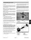
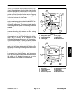
Cutting Reel Motor Rotor Removal
1. Remove gearbox cover and output gear from motor
assembly (see Cutting Reel Motor Service in the Ser-
vice and Repairs section of this chapter).
2. Remove screws that secure motor cover. Do not re-
move cover from motor assembly because it will be re-
moved with reel motor rotor during rotor removal.
3. Secure tool set base plate to motor housing with four
(4) of the cover screws.
4. Install threaded shaft into base plate.
IMPORTANT: The rotor magnets are very powerful
andcan causethe rotorto shiftposition veryrapidly
duringremoval. Becautiousduring rotorremovalto
prevent component damage or personal injury.
5. Turn threaded shaft with handle to remove rotor and
motor cover from motor housing. Support rotor to pre-
vent it from falling from housing during removal.
6. Leave threaded shaft installed in same position in
base plate for rotor installation purposes.
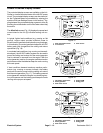
Cutting Reel Motor Rotor Installation
1. Secure tool set base plate to motor housing with four
(4) of the cover screws.
2. Make sure that threaded shaft is installed into base
plate so that the end of the threaded shaft prevents the
rotor body from entering the motor housing.
IMPORTANT: The rotor magnets are very powerful
and cancause therotorto shift position veryrapidly
during installation. Be cautious during rotor instal-
lation topreventcomponent damageor personalin-
jury.
3. While guiding rotor into motor housing, slowly rotate
threaded shaft to allow the rotor to be drawn into the
housing. Once rotor is fully installed into housing, re-
move tool set from motor housing.
Figure 6
1. Puller hub
2. Threaded shaft
3. Handle
1
2
3
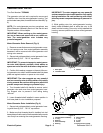
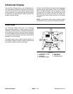
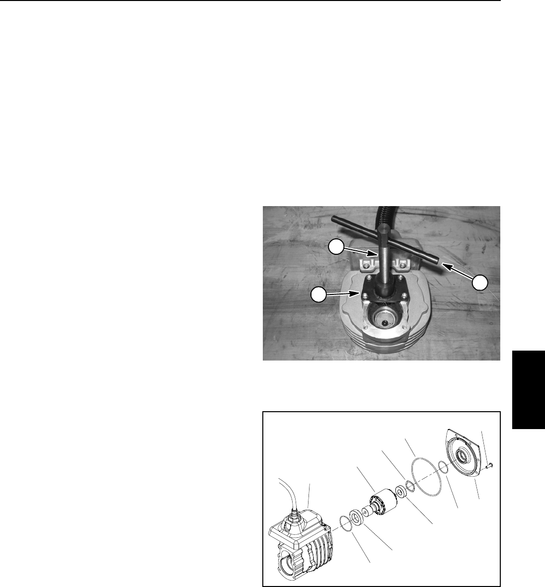
1. Screw (6 used)
2. Motor cover
3. O-ring
4. O-ring
5. Wave washer
6. Bearing
7. Rotor
8. Bearing
9. O-ring
10. Housing assembly
Figure 7
7
5
6
8
3
9
2
4
1
10
Electrical
System