


Reelmaster 5010- H Page 6 - 27 Chassis
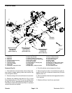
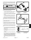
5. Remove lynch pin (item 12) and rear thrust washer
(item 13) from rear of pivot yoke. Slide pivot yoke as-
sembly from lift arm. Locate and retrieve front thrust
washer (item 13).
CAUTION
Be careful w hen removing tension from the tor-
sion spring onthe rearlift arms. Thespring isun-
der heavy load and may cause personal injury.
6. Remove tension from both torsion springs (items 14
and 15) on rear of lift arm pivot shaft.
A. Note on which shoulder stud (item 7) the torsion
spring end is attached for assembly purposes.
B. Insert nut driver or small piece of pipe onto the
end of the torsion spring that is secured to the shoul-
der stud.
C. Pushdown and rearwardon the springend to un-
hook the spring from the shouldered stud (item 7).
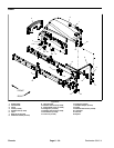
7. Remove two (2) flange head screws (item 6) that se-
cure housing (item 1) to machine. Remove housing, tor-
sionsprings(items14 and15)and two(2) washers(item
5).
8. Remove washer head screw (item 10) that secures
pivot shaft (item 9) to frame.
9. Support rear lift arm to prevent it from falling. Slide
pivot shaft from frame and lift arm. Remove rear lift arm.
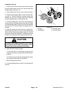
10.Inspect pivot shaft and replace if worn or damaged.
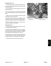
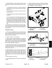
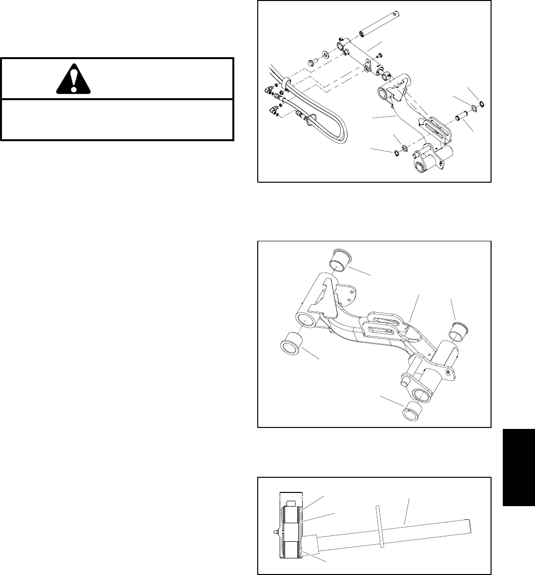
11.Inspect bushings in lift arm and pivot yoke for wear
ordamage. Ifnecessary, replaceb ushings (Figs.26and
27).
A. Use bushing removal tool t o extract both bush-
ings from the lift arm or pivot yoke. Take care to not
damage the bore.
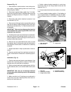
B. Clean the inside of the bore to remove any dirt or
foreign material.
C. Apply grease to the inside and outside of the new
bushings.
D. Use an arbor press to install the bushings into lift
arm or pivot yoke. Lift arm bushings should be
pressed until bushing flange is against lift arm bore.
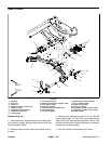
The upper pivot yokebushing should be pressed ful-
ly to the shoulder in the pivot yoke bore. The lower
pivot yoke bushing should be flush with the yoke
tube.
Figure 25
4
3
2
3
4
5
1
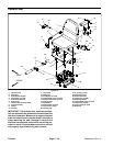
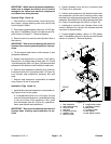
1. Lift arm (#2 shown)
2. Lift cylinder
3. Retaining ring
4. Thrust washer
5. Cylinder pin
1. Rear lift arm (#2 shown)
2. Pivot yoke bushing
3. Lift arm bushing
Figure 26
2
1
3
2
3
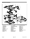
1. Pivot yoke
2. Upper b ushing
3. Pivot yoke shoulder
4. Lower b ushing
Figure 27
1
2
3
4
Chassis