


Reelmaster 5010- H
Cutting Units
Page 7 - 14
Service and Repairs
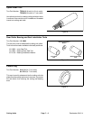
Cutting Reel Motor
NOTE: If electrical problems exist with a cutting reel
motor, a fault should have occurred that would be indi-
cated by a fault code on the InfoCenter Display. Before
considering that reel motor service work is necessary,
check for anyexisting faultcodes thatindicate problems
withareelmotor.
IMPORTANT: When performing service or mainte-
nance on the cutting reel motors, take care to not
damage the motors or electrical connections.
For information on removal, installation and service of
the cutting unit motors, see Cutting Reel Motor and Cut-
ting Reel Motor Service in the Service and Repairs sec-
tion of Chapter 5 - Electrical System.
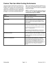
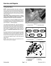
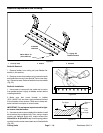
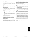
The cutting unit side plates (Fig. 19) have threaded in-
sertsatt he locationsused forthecapscrews thatsecure
the reel motor. Check the condition of the threaded in-
sertswheneverthecuttingreel motoris removedandre-
place inserts if damage is found. Inserts should be
torquedfrom 35to 40ft- lb(48to 54N-m) during instal-
lation.
For proper lubrication ofthe reel motorsplines,a grease
fitting (item 3 in Fig. 19) must be installed in the cutting
unit side plate on the reel motor side of the cutting unit.
On the non- drive side plate, a set screw (item 4 in Fig.
19) should be installed so that it is flush with the side
plate surface.
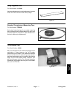
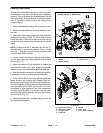
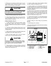
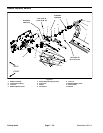
NOTE: RefertoFigure18forcorrectplacementofcut-
ting unit reel motors and weights.
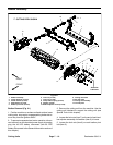
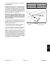
1. Cutting reel motor 2. Cap screw (2 used)
Figure 17
1
2
1. Reel motor location 2. Weight location
Figure 18
FRONT
4 1 5
32
12
1. Side plate (LH shown)
2. Threaded insert
3. Grease fitting
4. Set screw
5. Relief fitting
Figure 19
2
3
1
5
4
2
35 to 40 ft- lb
(48to54N-m)