


Reelmaster 5010- H Page 6 - 7 Chassis
6. Slide rubber bellows up steering column to allow ac-
cess to fasteners that secure steering column to ma-
chine.
7. Support steering control valveto preventit fromshift-
ing during steering column removal.
8. Loosen and remove four (4) socket head screws
(item 6) that secure steering control valve to steering
column.
9. Loosen and remove four (4) socket head screws
(item 11) and flange nuts (item 9) that secure steering
column to machine.
10.Slide steering column assembly from steering con-
trol valve and machine.
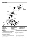
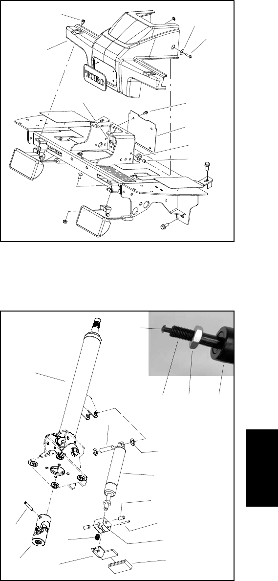
11.Disassemble steering column assembly as needed
using Figure 6 as a guide.
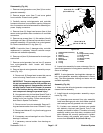
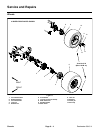
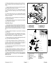
Installation (Fig. 4)
1. Assemble steeringcolumnusing Figure6as aguide.
Afterassembly,makesurethatreleasepinonendofcyl-
inder shaft is positioned against the pedal. Jam nut on
cylinder shaft can be used to adjust location of release
pin.
2. Apply antiseize lubricant to input s haft of steering
control valve.
3. Slide steering column onto steering control valve.
Secure steering column in place with four (4) socket
head screws (item 11) and flange nuts (item 9).
4. Secure steeringcontrolvalve tosteeringcolumnwith
four (4) socket head screws (item 6).
5. Slide rubber bellows to bottom of steering column.
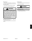
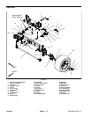
6. Place rubber bushings and spacers into holes of
platform shroud (Fig. 5). Position platform shroud in
place and secure with removed fasteners.
7. Thoroughlyclean taperedsurfaces ofsteeringwheel
and steering column.
8. Apply antiseize lubricant to splines of steering col-
umn takingcare to keep antiseize lubricantfrom column
taper. Slide steering wheel onto steering column.
9. Secure steering wheel to steering column with flat
washer and lock nut. Torque hex nut from 20 to 26 ft- lb
(28to35N-m).
10.Install steering wheel cover to steering wheel.
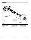
1. Washer (2 used)
2. Screw (2 used)
3. Screw (6 used)
4. Platform shroud
5. Lock nut (2 used)
6. Cover plate
7. Bushing (2 used)
8. Spacer (2 used)
Figure 5
3
4
1
2
5
3
6
7
8
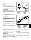
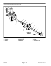
Figure 6
1. Steering column
2. Pin
3. Universal joint
4. Pin
5. Lock washer (2 used)
6. Cylinder
7. Bolt (2 used)
8. Pin
9. Pedal block
10. Pedal cover
11. Pedal
12. Spring
13. Release pin
14. Cylinder shaft
15. Jam nut
2
3
4
5
6
1
7
8
9
10
12
11
6
13
14 15
Chassis