


Reelmaster 5010- H Page 5 - 73 Electrical System
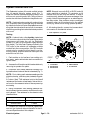
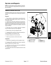
Fuel Actuator
The fuel actuator used on your Reelmaster must be en-
ergized by the TEC controller f or the diesel engine to
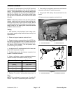
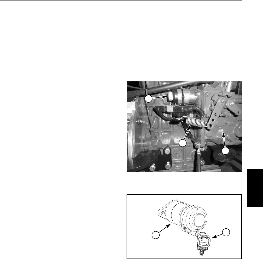
run. The actuator is mounted to the injection pump on
theengine(Fig.76).
The fuel actuator and TEC controller work together to
maintain engine speed by adjusting the fuel delivery to
the engine. A sensor in the motor/generator provides
thegenerator/enginespeed totheTEC controllervia the
CAN- bus.Ifthere isa changein enginespeed(e.g. load
conditions change, engine speed switch pressed byop-
erator), the TEC controller modifies the electrical output
to theactuator whichadjustsfuel asrequiredto maintain
engine speed.
The TECcontrollermonitors theoperationof thefuel ac-
tuator. If the TEC controller detected a fuel actuator
problem during engine operation, the InfoCenter Dis-
play can be used to identify the fault (see Fault Codes
in the Troubleshooting section in this chapter).
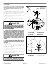
NOTE: If a problem with the fuel actuator or circuit
wiringexists, theextensionspring attachedto theactua-
tor bracket andenginespeed controlleverwill cause the
engine to run at high idle (3150 RPM) with the engine
mechanical governor maintaining engine speed. In this
situation, the control arm mounted engine speed switch
will not change enginespeed and a faultcode should be
displayed on the InfoCenter Display.
Testing
1. Park the machine on a level surface, engage the
parking brake, lower the cutting units and stop the en-
gine. Remove the key from the ignition switch. Open
hoodtogainaccesstoengine.
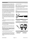
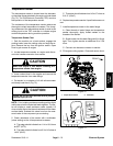
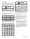
2. Locate fuel actuator and disconnect wire harness
connector from fuel actuator.
NOTE: The fuel actuator may be tested in place or
removed from the engine for testing.
3. If the actuator is removed from the engine, make
sure that the actuator plunger moves freely and is free
of dirt, debris and corrosion.
NOTE: Prior to taking small resistance readings with a
digital multimeter, short the test leadstogether. Theme-
ter will display a small resistance value (usually 0.5
ohms or less). This resistance is due to the internal re-
sistance of the meter and test leads. Subtract this value
from the measured value ofthe componentyou aretest-
ing.
4. Using a multimeter (ohms setting), measure resis-
tancebetween thetwo terminalsin thefuel actuatorcon-
nector. Resistance should be from 5.0 to 5.5 ohms.
5. If ac tuator coil resistance is incorrect, replace fuel
actuator.
6. When testingiscomplete, connectwireharnesscon-
nector to the fuel actuator.
7. Lower and secure hood.
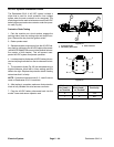
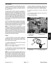
1. Injection pump
2. Fuel actuator
3. Extension spring
Figure 76
1
2
3
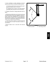
1. Fuel actuator 2. Actuator connector
Figure 77
1
2
Electrical
System